
How Many Axis in CNC Turning Machine? Configurations Explained
Axis count decides which features you can cut in one setup, how many fixtures you need, and where cost lands. This guide walks through 2-axis to 5-axis turning, the tolerances each holds, and how to pick a configuration for a specific part.
In this article
- 1
- 2
- 3
- 4
- 5
- 6
- 7
- 8
Key takeaways
What an axis means in cnc turning
In a turning center, an axis is a programmable direction of relative motion between the tool and the workpiece. The workpiece spins on the spindle, and the tool moves along controlled paths to remove material. A 2-axis lathe controls only X and Z. X is radial: it sets the diameter. Z is longitudinal: it sets the depth along the part. Those two directions cover every feature that is rotationally symmetric.
Extra letters on the spec sheet are not motor counts. They describe the kind of motion, not the number of servo drives. The C-axis rotates the spindle itself, so the part can stop at a precise angle. The Y-axis moves the turret or tool post perpendicular to the X axis, off the part centerline. The B-axis tilts the tool around a perpendicular axis, so a milling spindle can approach at an angle.
That distinction matters when you read a machine brochure. A "3-axis lathe" usually means X, Z and C. A "4-axis lathe" can mean either X, Z, C and Y, or it can mean two turrets on the same X and Z travels. Two turrets cut cycle time. Y adds geometry. Those are different purchases. Ask which interpretation the builder uses before you compare quotes.
Axes also split into linear and rotary types. Linear axes travel in a straight line and report position in millimeters. Rotary axes turn and report position in degrees. A live tool spinning in the turret is not an axis. It is a driven tool. It needs C-axis indexing to cut on the part face, but the spinning itself is separate from axis control.
2-axis and 3-axis: axis in CNC turning for round parts
A 2-axis lathe is the workhorse of turned parts. X and Z travel, one spindle, usually one turret. It holds ±0.005 mm on diameter without much effort when the material is stable and the tool is fresh. Cycle times are short because there is no indexing and no second operation. For a shaft with shoulders, grooves and a chamfer, nothing beats it on cost.
The limit shows up as soon as a feature leaves the centerline. A cross hole, a milled flat, an axial slot, or a hex on the end face cannot be cut by X and Z alone. On a 2-axis machine you either move the part to a mill, or you add a fixture that indexes the part by hand. Each move adds setup error and queue time. On a 50 mm shaft, a second op can easily add 0.02 mm of position error between features.
A 3-axis lathe adds the C-axis. The spindle becomes a programmable rotary axis, so the part indexes to any angle and locks. A live tool then drills, mills or taps at that position. This is the point where turned parts start to look like milled parts. Cross holes, axial holes on a bolt circle, flats, and hex features all run in the same setup.
C-axis work has a hard boundary. The tool always approaches from the side of the part, so a pocket wall that must stay square to the centerline is fine, but a contoured pocket floor at an angle is not. If the feature needs the tool to reach around a corner or under a shoulder, a 3-axis machine cannot do it. That is Y-axis and B-axis territory.
Accuracy on the C-axis depends on the lock and the encoder. A 0.001° resolution sounds impressive, but the real number is repeatability after clamping. A worn curvic coupling can drift a few hundredths of a degree, which becomes 0.01 mm of position error on a 40 mm diameter. Check the C-axis repeatability spec, not just the resolution.
4-axis and 5-axis: when axis in CNC turning pays off
A 4-axis lathe adds the Y-axis. The tool now moves off the centerline, so a milling cutter can plunge into the side of the part and cut a real pocket or a keyway. This is not a compromise version of milling. On a good Y-axis machine, a 10 mm end mill can cut a slot 20 mm deep in a 40 mm shaft with the same rigidity you would get on a small vertical mill.
The practical win is fewer setups. A part with a cross hole, a keyway and a milled flat used to run on a lathe plus a mill plus a fixture. With Y-axis it runs on one machine in one cycle. Position error between features drops because the part never moves. On a typical hydraulic manifold, that can cut total tolerance stack from 0.03 mm to under 0.01 mm.
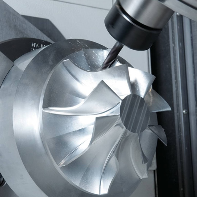
A 5-axis turning center adds the B-axis, which tilts the tool. Now the cutter can approach at an angle, so angled holes, undercut contours, and compound surfaces become single-setup work. Aerospace brackets, medical bone plates, and complex valve bodies are the usual candidates. The trade is programming time and machine cost.
Not every part benefits. If the geometry is rotationally symmetric, a 5-axis machine adds nothing except a higher hourly rate. If the part has one cross hole and nothing else, a 3-axis lathe with C-axis is enough. The decision rule is simple: count the features that need the tool to leave the centerline or approach at an angle. Two or fewer, stay with 3-axis. Three or more, and a 4-axis or 5-axis machine usually pays back within the first production run.
Rigidity also changes with axis count. Every additional axis is another set of bearings and another source of deflection. A 5-axis machine with a long B-axis overhang can chatter where a 2-axis lathe would cut clean. Keep tool overhang short, use the largest shank the holder allows, and check the surface finish on a test cut before committing a full run.
How material and part size change the axis choice
Soft, free-machining materials forgive a lot. Aluminum 6061, brass C36000 and 12L14 steel cut cleanly on any axis count. The limits are tool life and chip control, not machine rigidity. Stainless 316 and 17-4PH work-harden, so a Y-axis or B-axis machine with a rigid setup and constant feed is safer than a light 2-axis lathe that has to stop and index.
Titanium Ti-6Al-4V and Inconel push the other way. Heat stays in the cut, so you want short tool overhang, high-pressure coolant, and a machine that can hold a rigid toolpath. A 2-axis lathe with a well-supported tool can hold ±0.005 mm on Ti-6Al-4V, but a 5-axis machine with a long B-axis overhang may not. Match the axis count to the material, not just the geometry.
Part size sets the practical limit too. Long shafts above 500 mm need a steady rest or a tailstock, and on a 2-axis lathe that is routine. On a mill-turn or 5-axis machine, the same part may need special workholding that costs more than the machining. For parts up to 4,000 mm, turning on a 2-axis or 3-axis machine is usually the fastest path.
Plastic parts behave differently again. POM and PEEK move with temperature, so a C-axis index that heats the part can shift dimensions. Keep coolant on, let the part stabilize, and check the first article before running the batch. Carbon fibre is abrasive, so use diamond-coated tools and expect shorter tool life on any axis count.
Cost, lead time and axis count
Axis count drives hourly rate, but not linearly. A 2-axis lathe is the cheapest per hour. A 3-axis lathe with C-axis costs more because of the live tooling and the encoder. A 5-axis turning center costs the most per hour, but it can replace two or three operations, so the total part cost sometimes drops. Always compare total cost, not hourly rate.
Setup time is the hidden cost. Every extra setup adds fixture time, first-article inspection and queue time. On a small batch, that can double the effective cost. On a large batch, the per-part setup cost fades and cycle time dominates, so a faster 2-axis machine wins on simple parts even if a 5-axis machine is available.
Lead time follows the same logic. A 2-axis turning job with a simple fixture can start within 24 hours. A 5-axis job with complex workholding may need a day of programming and a custom fixture before the first chip. If the schedule is tight, ask whether a 3-axis lathe with two setups can meet the tolerance.
Quality control scales with axis count too. More axes mean more positions to verify. On a 5-axis part, check the C-axis and B-axis positions on the first article, not just the linear dimensions. A 0.01° error on the B-axis becomes a visible step on a contoured surface.
Step by step: pick the right axis count
- 1List every feature that leaves the centerlineMark cross holes, milled flats, keyways, axial slots, angled holes and compound surfaces on the drawing. Features on the centerline do not drive axis count.
- 2Count how many need an angled approachIf a feature needs the tool to reach around a shoulder or cut a sloped floor, it needs B-axis. If it only needs to move off center, Y-axis is enough.
- 3Check the tolerance stack between featuresIf features must hold ±0.01 mm relative to each other, one setup beats two. If ±0.05 mm is acceptable, a second op on a mill is fine.
- 4Estimate annual volumeUnder 500 parts, a 3-axis lathe with C-axis plus a mill is often cheaper than a 5-axis machine. Over 2,000 parts, the setup savings usually justify 4-axis or 5-axis.
- 5Confirm material machinabilityStainless, titanium and Inconel need rigid tooling. Do not use a long-overhang B-axis setup for a work-hardening alloy.
- 6Check the workholding envelopeA Ø400 mm rotary table and 4,000 mm maximum processing size exist in our fleet, but not every machine takes every part. Match the part to the machine travel.
- 7Run a first article before the batchCut one part, measure every feature, and confirm the C-axis repeatability and surface finish. Then release the run.
CNC turning axis configurations compared
Typical use by axis count
| Config | What it adds | Best for | Watch out for |
|---|---|---|---|
| 2-axis | X and Z only | Shafts, bushings, bolts, spacers | No off-center features in one setup |
| 3-axis | C-axis spindle indexing | Cross holes, flats, bolt-circle holes | Tool always approaches from the side |
| 4-axis | Y-axis off-center travel | Keyways, pockets, cross slots | Higher machine rate than 2-axis |
| 4-axis twin turret | Second turret on same X and Z | High-volume simple parts | Does not add geometry, only speed |
| 5-axis | B-axis tool tilt | Angled holes, undercuts, compound surfaces | Programming time and cost jump |
| Mill-turn | Turning plus milling spindle | Complex parts with many features | Workholding can dominate cost |
Frequently asked questions
Can a 2-axis lathe make a part with a cross hole?
Yes, but it needs a second setup on a mill or a manual indexing fixture. That adds position error between the hole and the turned diameter, often 0.02 mm or more.
If the cross hole must hold a tight relationship to the turned features, a 3-axis lathe with C-axis is the better choice.
Is a 4-axis lathe always better than a 3-axis lathe?
No. A 4-axis lathe with Y-axis adds off-center milling, which is real capability. But a 4-axis twin-turret lathe only adds a second turret on the same X and Z travels. It cuts cycle time, not geometry.
Ask the builder which type you are buying. The two configurations solve different problems.
What tolerance can multi-axis turning hold?
Our turning work holds ±0.005 mm on diameter, with surface finishes from Ra 0.2–0.8 μm on fine work and Ra 0.8–1.6 μm on standard production parts.
The achievable number depends on material, tool overhang and how many axes are moving at once. A rigid 2-axis setup can beat a loose 5-axis setup on the same part.
Which materials can be turned on a multi-axis machine?
Aluminum 6061, 7075 and 2024; stainless 303, 304, 316L and 17-4PH; steel 1045, 4140 and 4340; brass C36000; titanium Ti-6Al-4V; and plastics such as POM, PEEK and PA.
Work-hardening alloys and titanium need rigid tooling and controlled feeds. Send the drawing and we will confirm the axis count and the tooling plan.
How fast can a multi-axis turning quote come back?
We return a quotation and a free DFM analysis within 12 hours. Production can start within 24 hours after drawing release, and parts typically ship in 3–5 days.
Complex 5-axis workholding may add a day for fixture design. We will tell you that upfront rather than after the order.
Do you offer prototyping on multi-axis turning machines?
Yes. There is no minimum order quantity, so one prototype and a 10,000-part run both go through the same process.
Uploads are secure and confidential, and an NDA is available on request.
Send your drawing, get the axis count and a quote
Tell us the features and the tolerance. We will confirm whether 2-axis, 3-axis, 4-axis or 5-axis turning fits, and return a quotation with free DFM analysis within 12 hours.
12-hour quote100% inspectionNo minimum order±0.005 mm tolerance
More CNC turning notes
We publish setup notes, tooling trials and inspection data from the factory floor.











