
How Many Control in CNC Machine? 5 Control Types Explained
If you are quoting a machined part, the answer to how many control in cnc machine matters more than the machine label. This guide walks through the five control groups on a CNC machine, what each one actually commands, and how to decide which combination your part really needs. Written for engineers and buyers who need to judge a quote, not just read a brochure.
In this article
- 1
- 2
- 3
- 4
- 5
- 6
- 7
Key takeaways
What Counts as a Control in a CNC Machine
People ask how many control in cnc machine and expect a single number. In practice the CNC controller runs several closed control loops at the same time. The axis loop moves the table or spindle along X, Y and Z. The spindle loop holds a commanded rpm under cutting load. The feed loop synchronizes the axis velocity to the programmed feed rate. Tool selection and coolant sit on top as logic controls rather than motion loops, but they still count as controlled functions.
A typical vertical machining center therefore carries five distinct control groups: axis, spindle, feed, tool, and coolant. A lathe adds a second axis pair (X and Z for the turret, plus C and Y on mill-turn models) and swaps the tool control for a turret index. The count stays close to five; what changes is how many axes each group drives.
This matters commercially. When a shop quotes a part, the axis count decides whether the part needs one setup or three, and setup count is often the largest single line in a small-batch quote. The spindle and feed loops decide whether the surface finish lands at Ra 0.8–1.6 μm straight off the tool or needs a second pass.
So the useful answer is not a fixed integer. It is: count the control groups you need to command for your geometry. Everything else is machine marketing.
- 1Axis controlLinear and rotary motion, from 3 axes up to 5 simultaneous axes.
- 2Spindle controlSpeed and direction, often with through-spindle coolant on deep pockets.
- 3Feed controlProgrammed feed rate, with override and adaptive feed on some controllers.
- 4Tool and coolant controlWhich tool is in the cut, and where the coolant lands.
Axis Control: 3, 4 or 5 Simultaneous Axes
Axis count is the control most engineers mean when they ask how many control in cnc machine. A 3-axis mill moves the part in X, Y and Z while the tool stays vertical. It handles plates, housings, brackets and most prismatic parts well. Our 3-axis fleet runs travels of 750 × 1,150 × 550 mm and 600 × 600 × 600 mm, which covers a wide range of enclosure and manifold work.
A 4-axis machine adds a rotary table, usually turning about X. The part can be indexed to four sides without a human touching the fixture. That single added control removes two re-fixtures on a typical four-face part, and every re-fixture is a chance to lose 0.02 mm of position. We run 12 four-axis mills with a Ø400 mm rotary table.
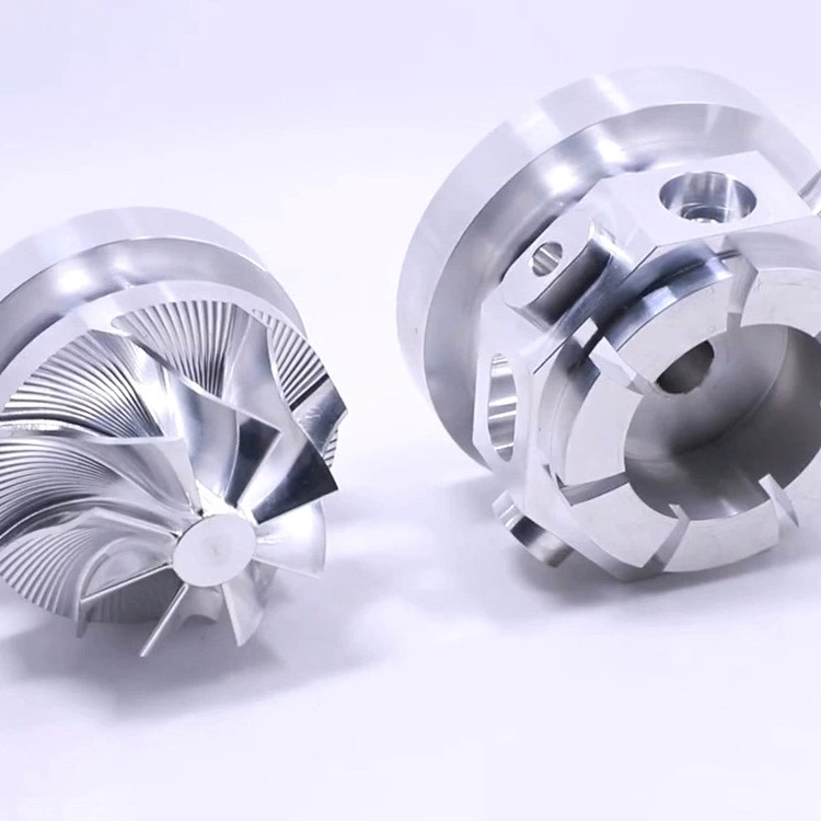
A 5-axis machine adds a second rotary axis, so the tool can tilt as well as the table. Sixteen simultaneous 5-axis machining centers in our shop cut impellers, turbine housings, medical bone plates and engine parts in one setup. Simultaneous is the key word: 3+2 positioning is not the same thing, and it will not produce a true sculpted surface in one pass.
When is more axes the wrong call? When the part is a flat plate with holes on one face. A 5-axis cycle on that part costs more per hour and buys nothing. Keep the simple part on the simple machine.
- 1Pick 3-axisPrismatic parts, one dominant face, tight budget, fast turnaround.
- 2Pick 4-axisParts with features on 3–4 sides, or round parts needing cross-holes.
- 3Pick 5-axisSculpted surfaces, undercuts, or five faces in a single setup.
Spindle, Feed and Tool Control Working Together
Spindle speed sets surface speed at the cutting edge. Run 6061 aluminum at 300–500 m/min surface speed and the chips fly clear. Run 316L stainless at the same number and you burn the insert in minutes. The controller holds the commanded rpm, but the toolpath decides whether that rpm is useful. Constant surface speed mode on a lathe lets the spindle ramp up as the tool moves toward center.
Feed rate is the second half of the equation. Feed per tooth, not feed per minute, is what the cutter feels. A 10 mm carbide end mill in aluminum typically runs 0.05–0.15 mm per tooth; the same cutter in titanium drops to 0.02–0.05 mm per tooth with heavy coolant. If the controller has adaptive feed control, it can slow the feed automatically when the tool enters a full-width cut.
Tool control decides which cutter enters the cut and when. Automatic tool changers hold 20–40 tools on our machining centers and swap in a few seconds. That matters on parts with many hole sizes. A part with 12 drilled holes in 4 diameters runs as one program with 4 tools, not 12 manual changes.
These three controls are not independent. Change the tool and the feed and speed windows change with it. A setup sheet that lists only rpm is half a setup sheet.
Coolant, Probing and In-Process Control
Coolant control looks minor until you cut a 120 mm deep pocket in 17-4PH. Flood coolant removes heat; through-spindle coolant blasts chips out of the hole. Air blast alone works for plastics and some aluminum jobs, but not for deep stainless pockets. Choosing the wrong coolant mode is a common reason a first article comes out with a poor floor finish.
Probing is the control that catches errors before the part is finished. A touch probe measures the stock position, offsets the work coordinate, and can check a critical bore after roughing. On a run of 200 parts, in-process probing is what keeps dimensions inside ±0.005 mm without pulling every part to a CMM.
Thermal drift is the quiet variable. A spindle running for four hours grows a few microns. Shops that hold tight tolerances on long runs either warm up the machine before the first cut or probe mid-run to correct for drift. Both are control decisions, not machine specifications.
When a buyer sends a drawing with a ±0.005 mm tolerance on one bore and open tolerances elsewhere, the right move is to probe that bore and leave the rest to standard inspection. Spending probe time on every feature raises cost for no benefit.
Step by Step: Choosing the Right Control Set for a Part
- 1Count the faces you must machineList every face, hole and pocket on the drawing. If features sit on more than two sides, a 3-axis machine needs extra fixtures. Three or four sides generally justify 4-axis; five or more sides or any undercut points to 5-axis.
- 2Check for undercuts and sculpted surfacesStraight walls and flat floors run on 3-axis. Curved blades, draft-angle turbine forms or side-entry slots need the tool to tilt, which means simultaneous 5-axis. 3+2 indexing will leave witness marks on a continuous curved surface.
- 3Set the tolerance per feature, not per partMark the features that need ±0.005 mm and leave the rest at general tolerance. Probe the critical features in-process. Probing everything adds cycle time and does not improve the result.
- 4Pick the material window for speed and feedAluminum 6061: 300–500 m/min, 0.05–0.15 mm/tooth. Stainless 316L: 120–180 m/min, 0.03–0.08 mm/tooth. Titanium TC4: 40–60 m/min, 0.02–0.05 mm/tooth with high-pressure coolant.
- 5Decide on coolant mode before quotingPocket depth over 3× tool diameter in steel or stainless needs through-spindle coolant. Shallow cuts and plastics run fine on flood or air blast. This choice affects cycle time, so it belongs in the quote.
- 6Plan tool changes into the programGroup features by tool, not by drawing order. A part with 4 hole diameters should run one tool per diameter across all holes. Random tool order adds minutes per part and wears the changer.
- 7Verify the first article against the setup sheetCheck the probed features and one open-tolerance feature. If the open feature drifts but the probed feature holds, the issue is thermal or fixture-related, not the program. Fix the cause before running the batch.
Axis Control Comparison for Common Part Types
Use this table to match part geometry to the axis control set before you request a quote.
| Part type | Best axis control | Typical tolerance | Why |
|---|---|---|---|
| Flat plate with drilled holes | 3-axis | ±0.05 mm | One face, no re-fixture needed |
| Four-sided housing | 4-axis with rotary table | ±0.02 mm | Indexes four faces in one setup |
| Impeller or turbine blade | 5-axis simultaneous | ±0.005 mm | Tilting tool follows the curve |
| Medical bone plate | 5-axis simultaneous | ±0.005 mm | Sculpted contour, thin walls |
| Round shaft with cross-holes | 4-axis or mill-turn | ±0.02 mm | Rotary index positions cross features |
| Large frame 3,000 mm long | 3-axis, 4,000 mm travel | ±0.05 mm | Long bed handles the envelope |
The Right Number of Controls Is the One Your Geometry Needs
Count the faces, undercuts and tight-tolerance features first. Then choose the axis count and control set. Not the other way around.
Frequently Asked Questions
Does a 5-axis machine always give better accuracy than a 3-axis machine?
No. Accuracy comes from the machine's geometric condition, the fixture and the thermal state, not the axis count. A well-maintained 3-axis machine holds ±0.005 mm on a prismatic part all day.
The 5-axis advantage is reach and single-setup access to complex surfaces. If your part has flat faces and through-holes, 5-axis adds cost without adding accuracy.
How many control in cnc machine does a lathe have compared to a mill?
A basic CNC lathe carries the same five control groups: axis, spindle, feed, tool and coolant. The axis pair is X and Z for the turret rather than X, Y and Z for a mill table.
A mill-turn center adds C and Y axes plus a second spindle, so it can run milling and turning in one program. That is more control loops, but still the same five functional groups.
What is the difference between 5-axis simultaneous and 3+2 positioning?
3+2 moves the rotary axes to a fixed angle, locks them, and then cuts with three linear axes. It is fast and rigid, and it works well for angled holes and flat faces.
Simultaneous 5-axis moves all five axes at once while cutting. Only simultaneous motion produces a continuous sculpted surface without witness marks. Ask which one the shop is quoting, because the cycle times differ.
Can coolant control affect the surface finish?
Yes, especially in deep pockets and in stainless or titanium. If chips are not cleared, the tool recuts them and the floor finish drops from Ra 0.8–1.6 μm to a smeared surface.
Through-spindle coolant is the usual fix for pockets deeper than three times the tool diameter.
How do I know if my part needs in-process probing?
If the drawing has one or two features at ±0.005 mm and the rest open, probing those two features in-process is enough. It catches drift before the batch runs.
If every feature is critical, the part probably needs a CMM report rather than probing on the machine.
What should I send with an RFQ to get the right control set quoted?
Send a 3D file plus a 2D drawing that marks critical tolerances and surface finish callouts. Note the material and any heat treatment.
We reply with a quotation and a free DFM analysis within 12 hours, and production can start within 24 hours of approval.
Send Your Drawing, Get a Control Plan Back
Upload your 3D file and 2D drawing. We reply within 12 hours with a quotation and a free DFM analysis, including the axis control set we recommend for your part.
12-hour quote100% inspectionNo minimum order quantityNDA on request
More from GreatLight
We publish setup notes, tooling trials and inspection data from the factory floor.











