
3-Axis CNC Machining Center: How It Cuts and Where It Stops
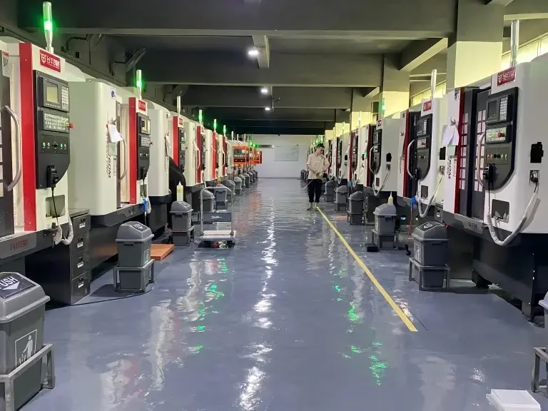
A 3-axis CNC machining center moves the spindle in X, Y and Z. The table stays flat, the tool approaches from one direction, and every hole you drill is parallel to that direction. This page explains the mechanism, the geometry it can and cannot reach, and the numbers we hold on 27 three-axis machines in Dongguan.
In this article
- 1
- 2
- 3
- 4
- 5
- 6
- 7
- 8
Key takeaways
What the three axes actually do
A 3-axis CNC machining center has three linear slides. X and Y move the worktable or the spindle in the horizontal plane. Z moves the spindle up and down. The cutting tool spins on one fixed axis, usually vertical on a VMC and horizontal on an HMC. Nothing rotates except the tool.
That single constraint drives everything else. The tool can only reach material along the direction it points. A flat end mill plunging in Z cuts a pocket whose walls are vertical. A ball nose cutter sweeping in X and Y leaves a scalloped surface whose height depends on stepover, not on axis count.
The controller (Fanuc, Siemens, Mitsubishi, or a similar industrial control) reads G-code and interpolates the three slides so the tool tip follows the programmed path. Circular interpolation in G02 and G03 is a two-axis move in the XY plane. Helical interpolation adds Z and lets you ramp into a pocket instead of plunging straight down.
Because the geometry is simple, the rigid body is simple too. Three-axis machines are stiffer per unit of cost than 4-axis or 5-axis machines of the same footprint. That stiffness shows up as less chatter on deep cuts and longer tool life on hard alloys.
- 1XY planeProfiles, slots, pockets and hole patterns produced by two-axis interpolation.
- 2Z axisDepth of cut, face milling, drilling and tapping along the spindle direction.
Which part shapes suit a 3-axis CNC machining center
The clean fit is a prismatic part: a plate, a block, a housing, a bracket, a manifold, a heat sink, a fixture plate. Features sit on the top face or on the bottom face, and you reach them by flipping the part once. If every hole is parallel to one of two directions, a 3-axis machine will cut it without a rotary table.
The second clean fit is a part with shallow 3D contour on one face. A mold insert, a stamping die, a lens housing. The tool steps over the surface in X and Y, and Z follows the contour. With a Ø6 mm ball nose cutter and a 0.1 mm stepover, we hold Ra 0.8–1.6 μm on aluminum without a polishing step.
The shape that does not fit is a part with undercuts, cross-drilled holes, or pockets on four or five faces. A 3-axis machine physically cannot swing the tool around the back of a boss. You either refixture the part three or four times, or you move it to a 4-axis or 5-axis machine.
A second family that does not fit is the long thin part with features on its side. Shafts, turbine blades, impellers and cams all need the work to rotate while the tool cuts. That is a 4-axis job at minimum.
- 1Good fitPlates, blocks, housings, brackets, manifold bodies, heat sinks, fixture plates.
- 2Marginal fitParts with one deep pocket and one shallow back-face feature.
- 3Poor fitImpellers, turbine blades, cams and any part with features on five faces.
Travel, spindle and workholding limits
Travel sets the largest part you can cut. Our three-axis machines come in three envelope sizes. The compact class runs 500 × 500 × 450 mm and 500 × 310 × 200 mm, which covers instrument panels, small housings and medical brackets. The medium class runs 750 × 1,150 × 550 mm and 600 × 600 × 600 mm, which covers most automotive and industrial parts.
The largest three-axis envelope we run is 4,000 × 400 × 150 mm. That is a long-travel machine for rails, beams, base plates and extrusion profiles. The 150 mm Z limit is the constraint to watch: it is fine for a flat part, tight for a deep one.
Spindle speed and torque decide the material. Aluminum 6061 and 7075 like 8,000–15,000 rpm and high feed. Stainless 316 and 17-4PH want lower rpm and more torque. Titanium TC4 (Ti-6Al-4V) needs flood coolant, moderate speed and a rigid setup, which three-axis geometry gives you for free.
Workholding is often the real limit, not the machine. A vise holds a block. Soft jaws hold a profile. A vacuum plate holds a thin plate that you cannot clamp from the side. When the part is thin and the tolerance is tight, we machine a fixture first and cut the part on the fixture in the second op.
Tolerance, finish and how setups stack error
On a single setup, a three-axis machine holds ±0.005 mm (±0.0002 in) on position and ±0.01 mm on size for most aluminum and stainless parts. That is machine capability, not a promise for every part. Part size, wall thickness and material all move the number.
Every additional setup adds a datum transfer. If you flip a part and pick up the new origin from a ground edge, you add roughly 0.005–0.02 mm of stack-up on features that span both setups. On a part with a 0.05 mm true position callout across two faces, two setups can eat the whole tolerance.
Surface finish depends on the cutter and the stepover, not axis count. As-machined aluminum comes off at Ra 1.6–3.2 μm with a sharp end mill and a moderate feed. A ball nose cutter with 0.1 mm stepover reaches Ra 0.8–1.6 μm. A fine stepover on a finishing pass reaches Ra 0.2–0.8 μm, which is usually good enough to skip a secondary polish.
The error to watch is not the machine, it is the fixture. A part that lifts 0.02 mm out of a vise jaw on the second op will show it as a step in the surface. We check runout and clamping force before the first cut, not after the last one.
Programming, toolpaths and the second op
CAM output for a 3-axis machine is straightforward. Almost every CAM package (Mastercam, Fusion, NX, Powermill) treats three-axis as the default case. The programmer picks tool diameter, stepover, stepdown, feed and speed, then posts G-code with no rotary moves.
Roughing uses the largest cutter the geometry allows, with stepdown around 0.5–1× tool diameter in aluminum and 0.2–0.4× in stainless. Adaptive or trochoidal paths keep radial engagement low so we can push feed without chatter. Finishing uses a smaller cutter and a tighter stepover.
The second op is where planning pays off. If the back face has two holes and a chamfer, we cut a soft-jaw pocket that matches the first-op profile. The part drops into the pocket, the jaw clamps on the machined side, and the back-face features come out concentric with the front. If the back face has a lot of material to remove, we machine a fixture plate instead.
Fixture design is a 3-axis problem, not a 5-axis one. A simple vise stop, a pair of soft jaws and a ground parallel bar cover most of the work. For a thin plate, a vacuum plate or a low-melt wax fixture holds the part flat while you face the back.
- 1Roughing stepdown0.5–1× tool diameter in aluminum, 0.2–0.4× in stainless and titanium.
- 2Finishing stepover0.1 mm for Ra 0.8–1.6 μm with a ball nose cutter.
- 3Second-op datumPick up from a machined surface, not from a saw-cut edge.
Materials a three-axis machine cuts well, and the ones it does not
Aluminum is the natural fit. We run 6061, 6061-T6, 2024, 5052, 5083, 6063, 6082, 7075 and ADC12 die-cast stock. Aluminum cuts fast, holds tolerance and lets a small cutter reach into tight corners without breaking.
Stainless is harder but still routine. 303 and 304 machine with sharp tooling and a rigid setup. 316 and 316L work-harden if the tool rubs, so we keep the feed up and the radial engagement down. 17-4PH (SUS630) in the H900 condition needs carbide and flood coolant. 440C and 420 are knife-steel grades that go to a heat-treat step after machining.
Steel covers 1018, 1045, 4130, 4140, 4340, A36 and tool steel. Brass and copper cover C101, C103, C110, C27400, C28000, C36000 and beryllium copper. Titanium covers TA1, TA2 and TC4. Plastics cover ABS, PC, PMMA, POM, PA, PEEK, PP, HDPE and carbon fiber.
The material that fights a 3-axis machine is not a metal, it is a thin flexible composite sheet. Carbon fiber plate thinner than 1 mm deflects under cutting force and chatters unless you back it with a sacrificial board. The same applies to thin PMMA and PC sheet.
3-axis vs 4-axis vs 5-axis: when to pick which
Read the part geometry first, then the tolerance, then the volume.
| Part feature | 3-axis | 4-axis | 5-axis |
|---|---|---|---|
| Features on one face | Best fit | Overkill | Overkill |
| Features on two opposite faces | Two setups | One setup | One setup |
| Cross-drilled holes | Second op or fixture | Good fit | Good fit |
| Contoured 3D surface | Good fit, longer cycle | Good fit | Best fit |
| Impeller or blade | Not possible | Not possible | Required |
| Deep pocket, 3× diameter | Possible with long tool | Better access | Best access |
| Tight true position across faces | Refixture error stacks | Lower error | Lowest error |
When to pick a 3-axis machine and when to move on
If your part is prismatic with features on one or two faces, a 3-axis CNC machining center is the cheapest and stiffest way to cut it. If it has undercuts, cross-drilled holes or features on four or five faces, move to 4-axis or 5-axis rather than stacking three or four setups.
Frequently asked questions
Can a 3-axis CNC machining center cut a part with a hole on the side?
Yes, but not in one setup. The part is flipped so the side face points up, then the hole is drilled in Z. The trade-off is a second datum transfer, which adds roughly 0.005–0.02 mm of position error on features that span both setups.
If the side hole has a tight true position related to a top-face bore, we would rather run the part on a 4-axis machine with a rotary table and cut both features in one setup.
What is the largest part a 3-axis machine can handle?
It depends on the machine envelope. Our compact three-axis machines run 500 × 500 × 450 mm and 500 × 310 × 200 mm. The medium class runs 750 × 1,150 × 550 mm and 600 × 600 × 600 mm.
The largest three-axis envelope we run is 4,000 × 400 × 150 mm for long, flat parts such as rails and base plates. The 150 mm Z travel is the limit to check before you send a deep part.
How tight a tolerance can a 3-axis machine hold?
On a single setup we hold ±0.005 mm (±0.0002 in) on position and ±0.01 mm on size for most aluminum and stainless parts. The number moves with part size, wall thickness and material.
Every extra setup adds 0.005–0.02 mm of stack-up. If a true position callout spans two faces and the tolerance is 0.05 mm, two setups can consume most of it.
Which materials cut well on a 3-axis machine?
Aluminum 6061, 7075 and 2024, stainless 303, 304, 316 and 17-4PH, steel 1018, 1045, 4140 and 4340, brass C36000, copper C110, titanium TC4, and plastics such as POM, PEEK and PC.
Thin carbon fiber and thin acrylic sheet need a backing board. Without it, the sheet deflects and chatters, and the finish suffers.
How long does it take to set up a 3-axis job?
A single-setup part with a vise and a few tools takes a few hours to program, fixture and prove out. A two-setup part with a custom fixture takes longer, because the fixture has to be machined first.
Quotation and a free DFM analysis come back within 12 hours, and production can start within 24 hours of a released order. Parts ship in 3–5 days.
Do I need a 5-axis machine for a contoured surface?
Not always. A shallow 3D contour on one face cuts fine on a 3-axis machine with a ball nose cutter and a tight stepover. We reach Ra 0.8–1.6 μm on aluminum with a 0.1 mm stepover.
A 5-axis machine earns its cost when the contour wraps around the part, when the tool needs to stay normal to the surface, or when a single setup must reach five faces.
Send us your part and we will tell you which axis count fits
Upload a STEP file and we come back within 12 hours with a quote, a DFM note and a recommendation on setup count. No minimum order quantity, from one prototype to 10,000+ parts.
12-hour quote100% inspectionNDA on request
More from the shop floor
We publish setup notes, tooling trials and inspection data from the factory floor.











