
Window Palletization CNC: How Robot Cells Load Machine Tools
This page explains what the loading window is, how a pallet system and a collaborative robot feed a CNC machine, and which part features make that cell worth building. It is written for manufacturing engineers and buyers who have to judge a layout before they commit floor space to it.
In this article
- 1
- 2
- 3
- 4
- 5
- 6
What the window palletization CNC loading window actually is
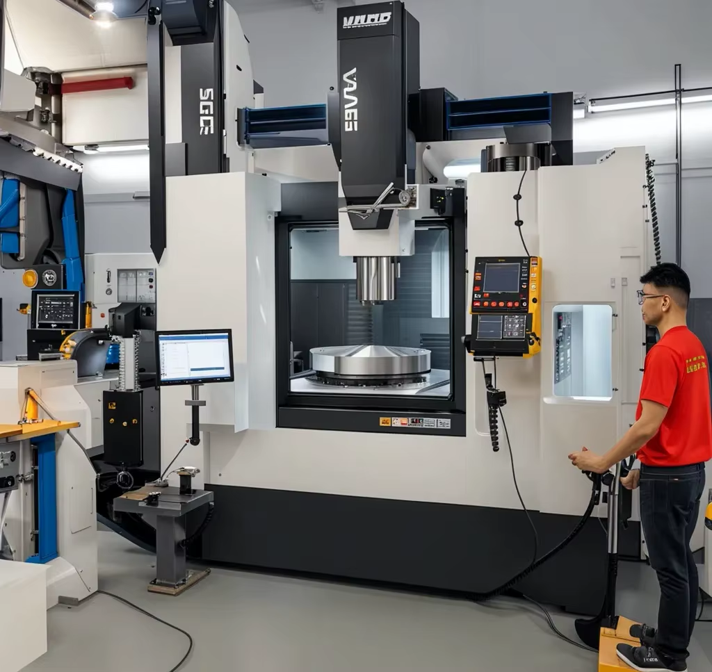
A CNC machine has an opening. On a vertical mill it is the front door; on a lathe it is the chuck side behind the sliding guard. That opening sets the size of the part and the gripper that can pass through it at once. Engineers call the usable envelope the loading window: the clear volume the handling device can enter, place a workpiece in, and leave without touching the enclosure.
The window is not the same as the machine travel. A mill with 750 × 1,150 × 550 mm of travel often has a much smaller door. A part can fit the table and still not fit the door opening. Check both before you draw the cell layout, because a gripper adds 80–150 mm on each side of the blank.
Two numbers define the window on a real cell. The first is clear height from the pallet top to the upper door edge. The second is the horizontal reach from the door plane to the fixture center. A collaborative robot rated at 1,300 mm reach may still fail if the fixture sits 200 mm behind the door on a low table.
Keep the window free of cables, chip conveyors and coolant lines. A cell that loads cleanly at 60% spindle load can jam once chips pile up. Leave 50 mm of clearance on every side of the swept path and re-check after the first production shift.
How pallets and cobots share the work
A pallet system moves parts to the machine; the robot only handles the last 300–600 mm. That split matters. The pallet does the travel over long distances, so the cobot arm stays short and stiff near the fixture. Short arms deflect less, which keeps placement repeatability inside ±0.05 mm at the fixture pin.
Pallet locating is where most repeatability is won or lost. Two hardened pins plus a flat rest pad give a repeatable position. Tapered pins self-center and tolerate 0.2–0.5 mm of approach error. Straight pins are stiffer but need the robot to place within 0.1 mm or the part will sit on a burr.
A collaborative robot is not a substitute for a pallet changer. It is best at picking one part, orienting it, and pressing it onto a fixture. If your cycle needs 20 parts per load, use a pallet stack and let the robot work only the top layer. This keeps the arm cycle under 10 seconds and the spindle cutting longer.
We see cells fail when the pallet and the robot are specified by different teams. Agree on the interface first: pallet top height, pin size, and the exact point the robot releases the part. That single datum prevents months of alignment work later.
Which part features make a cell worth building
A part suits a tending cell when it repeats. Fifty to 10,000 identical parts per year is the useful band. Below that, setup time dominates and manual loading is cheaper. Above it, a dedicated pallet changer or a hard automation line usually beats a cobot on cycle time.
Gripper features should be designed into the part, not added later. A 6–10 mm deep bore, a flat pad, or a shallow step gives the jaws a positive stop. Cast or forged blanks often have draft and flash; machine a small locating pad on the first operation so later operations have something clean to hold.
Weight matters more than size. Most collaborative robots handle 3–10 kg at full reach, less as the arm extends. A 4 kg part with a 2 kg gripper is already at the edge on a 5 kg rated arm. Weigh the blank, the gripper and the cable before you pick the robot.
Parts with thin walls, loose tolerances or heavy deburring needs are poor candidates. A cell will happily load a part that then needs 40 minutes of hand finishing, but you have automated the wrong step. Sort the finishing work first.
Tolerance, fixturing and the error budget
Build an error budget before you buy hardware. Robot placement, pallet pin clearance, fixture wear and thermal growth each add error. A typical cell runs: robot ±0.03 mm, pallet pin ±0.02 mm, fixture ±0.02 mm. That stack already reaches ±0.07 mm before the tool touches metal.
This is why cell-loaded parts usually carry ±0.05 mm or looser functional tolerances on the loaded features. When a drawing calls for ±0.005 mm, the critical features are normally cut in a second operation on a rigid fixture, or finished on a 5-axis machine with a single setup. Do not ask a cobot to hold a tenth of what the machine can hold.
Temperature is the quiet error source. A shop that swings 8 °C between morning and afternoon moves a 300 mm steel part by roughly 0.03 mm. Aluminum moves about twice as much. If the cell runs lights-out, the first parts of the shift and the last ones are not the same size.
Probing closes part of the gap. A spindle probe that measures the fixture each shift lets the control offset the work coordinate. It adds 20–40 seconds per load but removes the drift. For parts under ±0.02 mm, probing is not optional.
Pallet changer, cobot or manual: the real trade-offs
A pallet changer is fast and rigid. It moves a whole plate with several fixtures and swaps in a few seconds. It is poor at orienting a part or handling mixed sizes. Use it when the part count is high and the geometry is stable.
A cobot is flexible and slow. It can pick from a bin, flip a part, and load a second machine in the same cell. Cycle time per part is often 8–20 seconds. Use it when volumes are moderate and part mix changes, or when you need one arm to serve two machines.
Manual loading still wins in some shops. One operator with a hoist can load a 40 kg part in 30 seconds and inspect it at the same time. A cell that runs 200 parts a year will not repay its integration cost. Be honest about the volume before you buy.
Hybrid layouts work well. A pallet stack feeds the machine, and a cobot only loads the top plate. Or a cobot loads a 5-axis machine while a pallet changer serves a 3-axis mill next to it. Match the tool to the actual bottleneck, not to the catalog.
Window palletization CNC hardware at a glance
Compare the three common ways to feed a machine tool.
| Method | Best volume | Placement accuracy | Main limit |
|---|---|---|---|
| Manual loading | Under 500 parts/year | Depends on operator | Labor cost and fatigue |
| Collaborative robot | 500–10,000 parts/year | ±0.03–0.05 mm typical | Payload falls with reach |
| Pallet changer | Over 10,000 parts/year | ±0.01–0.02 mm typical | Fixed part geometry |
| Cobot + pallet stack | Mixed, 1,000–20,000/year | ±0.05 mm at fixture pin | Needs one shared datum |
Pick the layout that matches your volume
If your part repeats above 10,000 pieces a year and the geometry is stable, choose a pallet changer. If volumes are moderate and the part mix changes, choose a collaborative robot cell and keep the loading window clear.
Common questions
How much clearance does a cobot need at the machine door?
Plan for 50 mm of clearance on every side of the swept path, measured at the widest point of the gripper and the blank. The door frame, cables and chip guards are the usual contact points.
If the fixture sits deep inside the enclosure, add a reach check in the robot software before you cut metal. A dry run with a dummy blank costs an hour and prevents a crash.
Can a collaborative robot hold ±0.005 mm?
No. Repeatability of a typical cobot is around ±0.03 mm at the tool, and the pallet and fixture add more. The machine can hold ±0.005 mm on the cut, but the loaded position is looser.
When a feature needs ±0.005 mm, cut it in a second operation on a dedicated fixture, or finish it on a 5-axis machine in one setup.
What gripper features should we design into the part?
Add a 6–10 mm deep bore, a flat pad, or a shallow step that the jaws can register against. Avoid relying on a raw cast surface for location.
Machine a locating pad on the first operation so that later operations have a clean datum. That single pad often removes the need for a vision system.
Does the pallet need a special surface finish?
Contact pads should be ground or finely milled, around Ra 0.8–1.6 μm, so chips do not embed and lift the part. Sharp edges on the pad should be deburred to 0.2 mm or less.
Hardened pins and pads last longer in a chip-heavy cell. Replaceable pads are cheaper than re-machining the pallet body.
How do we keep accuracy stable across a lights-out shift?
Probe the fixture at the start of each shift and let the control update the work offset. This removes most thermal drift.
Keep the cell area at a steady temperature if the tolerances are tight. A 300 mm steel part moves about 0.03 mm over an 8 °C swing.
When is a cell simply not worth it?
Below roughly 500 parts a year, integration cost and programming time usually exceed the labor saved. Very heavy parts, parts needing long hand finishing, and parts with unstable geometry are also poor candidates.
Sort the finishing and inspection steps first. Automating a step that is not the bottleneck rarely pays back.
Send your part files for a cell-ready review
We review your drawings for gripper features, fixture datums and loading window clearance, then quote the machined parts that make the cell work. Quotation and free DFM analysis within 12 hours.
12-hour quote100% inspectionNDA on request
More from the shop floor
We publish setup notes, tooling trials and inspection data from the factory floor.











