
3D Printing Fuel Cell Devices: How AM Cuts Energy Processing Costs
Solid oxide and PEM stacks lose money at every pressure drop and every seal leak. This page explains how 3D printing fuel cell hardware changes flow geometry, part count and stack mass. For engineers deciding whether additive or CNC is the right route for a given plate, manifold or booster housing.
In this article
- 1
- 2
- 3
- 4
- 5
- 6
- 7
- 8
Key takeaways
What 3D Printing Fuel Cell Hardware Actually Changes
A fuel cell stack is a plumbing problem wrapped in an electrical problem. Hydrogen or reformate enters, air enters, water and heat leave, and every bend in that path costs pressure. Older designs used stamped or milled plates because those processes were available. 3D printing fuel cell hardware removes that constraint: a channel can widen, taper, split or turn inside a wall that a cutter could never reach.
The energy cost of a stack is not only the electrochemical reaction. It includes the compressor or blower work needed to push air through the cathode, the pump work for coolant, and the losses from any leak that bypasses the active area. When a printed flow field reduces pressure drop, the balance-of-plant hardware can be smaller. That is the real saving, and it shows up downstream of the stack, not in the stack bill of materials.
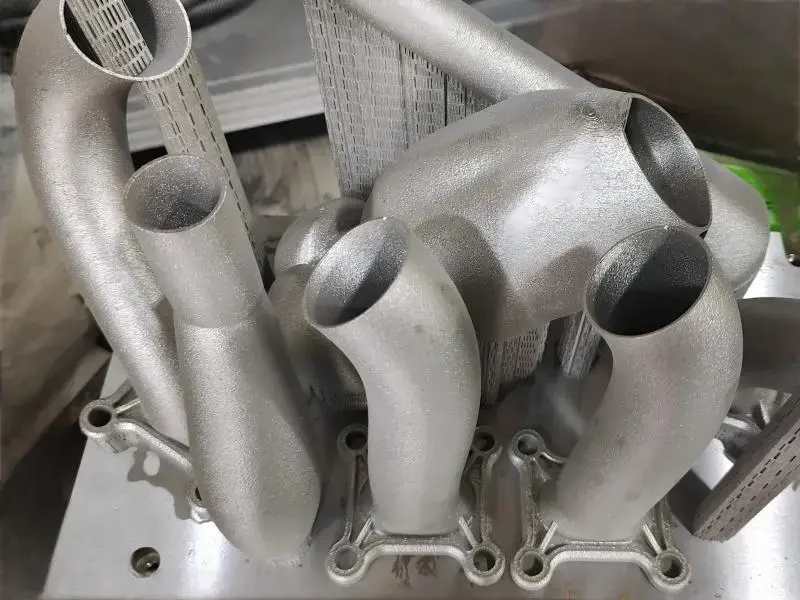
Additive also changes part count. A manifold that used to be seven brazed or welded pieces can become one printed body with internal channels. Fewer joints means fewer leak paths, fewer fixtures, and less assembly labor. In solid oxide designs, where operating temperature is 600–850 °C, fewer joints also means fewer places where thermal cycling can open a gap.
None of this makes additive a universal answer. Printed surfaces are rougher than machined surfaces, and roughness changes both flow resistance and gasket seating. The engineering question is which surfaces must stay machined and which can remain as-printed. That split is where most of the cost decision lives.
Flow Field Geometry and Pressure Drop
Cathode pressure drop is the single largest parasitic load in most air-breathing stacks. A serpentine channel with a 0.8 mm × 0.8 mm cross-section and a 20 m path can drop several kPa at typical stoichiometry. Printed designs can use parallel or interdigitated channels with a larger total cross-section while keeping the active area the same. The result is lower velocity for the same mass flow, and pressure drop falls roughly with the square of velocity.
Channel aspect ratio matters more than channel count. A wide, shallow channel (2 mm × 0.5 mm) has a lower wetted perimeter per unit area than a narrow, deep one, so it moves the same gas with less wall friction. Printing lets you build that shape directly. Milling a 2 mm wide, 0.5 mm deep channel in a 4,000 mm plate is possible, but tool deflection and chip evacuation make it slow and expensive at volume.
There is a limit. If channels get too wide, the gas short-circuits across the land and the active area starves near the ribs. A practical range for printed metal plates is 0.6–2.0 mm channel width with 0.4–0.8 mm depth. Keep the land-to-channel ratio between 0.8 and 1.4. Below that, contact resistance climbs; above it, mass transport suffers.
Flow uniformity across a large plate is the harder problem. A printed manifold can include a distribution plenum with graduated orifices, which is difficult to produce any other way. Test it with a flow bench and a pressure tap at each quadrant. If the spread is more than 10 percent, adjust orifice diameter before you commit to the design.
Materials, Flatness and Sealing Boundaries
Printed stainless such as 316L and 17-4PH covers most low-temperature PEM and SOFC interconnect work. Titanium Ti-6Al-4V is used where weight matters, and Inconel is reserved for high-temperature SOFC manifolds and reformer sections. Copper alloys appear in current collectors and cold plates because of thermal conductivity. Each material brings its own as-printed roughness: laser powder bed fusion typically lands between Ra 8 and Ra 15 μm on vertical surfaces.
That roughness is acceptable inside a flow channel but not on a sealing face. Gaskets and glass seals need flatness, usually 0.05 mm over the seal perimeter for PEM, tighter for SOFC glass seals. Printed plates rarely hold that as-built. The standard fix is to print oversize on the sealing face and machine it. This is where CNC enters the process, and it is not a compromise; it is the intended route.
Porosity is the other boundary. As-printed metal can retain 0.1–0.5 percent internal porosity depending on laser parameters. For hydrogen service, that is a leak path. Hot isostatic pressing closes most of it, but it also distorts thin plates and adds cost. A practical alternative is to print solid where hydrogen sits and keep the lattice only in coolant regions.
Surface finish targets differ by location. Active flow channels can run Ra 6–12 μm. Sealing faces should be machined to Ra 0.8–1.6 μm. Port bores and manifold interfaces need Ra 0.2–0.8 μm if they carry O-rings. Writing those three numbers on the drawing prevents most of the back-and-forth that slows a first build.
Why Most Fuel Cell Parts End Up Hybrid, Not Pure AM
A pure printed stack is rare in production. The common route is print the complex body, then machine the interfaces. That means printing stock on the sealing faces and port bosses, then holding the part in a fixture and cutting to ±0.005 mm. On a 4,000 mm plate, that requires a machine with enough travel and a fixture that does not spring the part during clamping.
Fixturing is the hidden cost. A thin printed plate 2–3 mm thick will deflect under clamp pressure. Vacuum chucks or low-melt fixturing work better than toe clamps. If the plate has internal channels, the vacuum must not pull through the walls, so a sealing gasket or a wax fill is needed. Plan this before the first cut, not after.
The hybrid route also lets you use the right material for each function. A printed 316L flow body can take a machined 17-4PH port insert, or a copper current collector can be joined to a stainless plate. This is normal in energy hardware. It is not a sign that additive failed; it is how the two processes divide the work.
For prototypes, hybrid is often the fastest path. One printed body plus a few machined faces can be in test within days of the final CAD. For production, the same split holds, but the machining step is moved into a dedicated cell with hard tooling. The geometry does not change; only the cycle time and the fixture do.
Where the Cost Saving Comes From
The saving is not in the powder price. Metal powder costs more per kilogram than wrought bar stock, and printing is slower than milling for simple shapes. The saving comes from three places: part consolidation, pressure drop reduction, and eliminated assembly steps. Each one is measurable, and each one only appears if the design uses additive for a reason.
Part consolidation is the easiest to quantify. If a manifold goes from seven parts to one, you remove six joints, six sets of fasteners, and the labor to align them. You also remove six leak paths. In a stack that must hold 0.5 bar hydrogen, that is not a minor gain. Fewer joints means a shorter leak-test cycle and a lower scrap rate at the end of the line.
Pressure drop reduction is harder to see on a quote but easy to see on a system diagram. If the cathode drop falls by half, the blower can be smaller. A smaller blower draws less power, which raises system efficiency. That benefit appears in the balance-of-plant cost, not the stack cost, so it is often missed in a parts-only comparison.
The third saving is design iteration speed. A printed flow field can be revised by changing a CAD file, not a die. For a new stack architecture, that means three or four flow variants can be tested in the time a stamped tool would take to cut. That speed has value even if the final production part is stamped.
When CNC Beats 3D Printing for Fuel Cell Parts
CNC wins when the geometry is simple and the tolerance is tight. Flat bipolar plates with straight channels, end plates, compression plates, port blocks and manifold flanges are usually faster and cheaper to mill. A 3-axis mill can hold ±0.005 mm on a flat plate and produce Ra 0.8–1.6 μm without a second operation.
CNC also wins when the material is hard to print. Beryllium copper, high-conductivity C110, and some tool steels print poorly or lose properties. For current collectors and cold plates, machining from wrought stock preserves thermal conductivity. Printing these parts can reduce conductivity by 20 percent or more depending on porosity and oxide content.
Volume changes the answer. For a single test stack, printing is often cheaper because there is no tooling. For a run of 10,000 identical flat plates, stamping or milling with a hard fixture will beat printing on unit cost. The crossover depends on channel complexity, but a practical rule is that simple flat plates cross over earlier than 3D flow fields.
There is also a repair and rework angle. A machined plate can be re-cut if a sealing face is nicked. A printed plate with internal channels usually cannot. If the design must survive field service, keep the critical sealing surfaces machined and replaceable.
3D Printing vs CNC for Fuel Cell Components
Compare by geometry, tolerance and volume. Pick the route that matches the part, not the process you already own.
| Part feature | 3D printing route | CNC route | Practical limit |
|---|---|---|---|
| Internal conformal channels | Preferred; no tool access needed | Difficult; needs split bodies | Channel width 0.6–2.0 mm |
| Sealing face flatness | Print oversize, then machine | Direct to 0.05 mm | Ra 0.8–1.6 μm after cut |
| Port bores and O-ring grooves | Print near-net, machine finish | Turn or mill in one setup | Ra 0.2–0.8 μm |
| Flat plates, straight channels | Possible but slow | Preferred; fast cycle | ±0.005 mm on 3-axis |
| Current collectors | Conductivity can drop | Wrought C110 preferred | Thermal path stays intact |
| One-off test stack | No tooling cost | Program and fixture cost | No minimum order quantity |
| 10,000+ flat plates | Unit cost stays high | Tooling pays back | Stamping or hard fixture |
| High-temp SOFC manifold | Inconel or 316L body | Machined flanges and seals | 600–850 °C service |
The Verdict
If the part carries internal flow geometry or replaces a brazed assembly, print it and machine the sealing faces. If it is a flat plate, an end plate or a current collector, machine it from wrought stock. The hybrid route is usually the cheapest overall, not a compromise.
Frequently Asked Questions
Can 3D printed metal parts hold hydrogen without leaking?
Yes, if the part is printed solid in the hydrogen-wetted region and the sealing faces are machined. As-printed laser powder bed fusion can retain 0.1–0.5 percent internal porosity, which is a leak path under pressure. Hot isostatic pressing reduces it, but it also distorts thin plates.
A practical route is to keep the flow body solid and reserve lattice or thin-wall features for coolant regions, then leak-test each part before assembly. For 0.5 bar hydrogen service, a helium leak test at 1 × 10⁻⁶ mbar·L/s is a common acceptance threshold.
What channel size works best for a printed flow field?
For metal powder bed fusion, a channel width of 0.6–2.0 mm and a depth of 0.4–0.8 mm covers most cathode and anode designs. Keep the land-to-channel ratio between 0.8 and 1.4.
Wider channels lower pressure drop but can starve the active area near the ribs. Narrower channels raise mass transport but increase wall friction. Test flow uniformity across the plate; a spread above 10 percent between quadrants means the manifold needs adjustment.
How flat does a fuel cell sealing face need to be?
For PEM gaskets, 0.05 mm over the seal perimeter is a common target. SOFC glass seals usually need tighter flatness because the seal is rigid and cannot conform to a gap.
Printed plates rarely hold that as-built, so the standard practice is to print stock on the sealing face and machine it. After machining, a finish of Ra 0.8–1.6 μm gives a reliable gasket seat.
Does printing reduce the cost of a fuel cell stack?
It can reduce system cost, but not always part cost. Metal powder costs more than wrought bar, and printing is slower than milling for simple shapes. The saving comes from part consolidation, lower pressure drop and fewer assembly steps.
If a manifold goes from seven parts to one, you remove six joints and six leak paths. If cathode pressure drop falls by half, the blower can be smaller. Both benefits appear outside the stack bill of materials.
What materials are available for printed fuel cell hardware?
316L and 17-4PH stainless cover most low-temperature work. Ti-6Al-4V is used where weight matters, and Inconel is reserved for high-temperature SOFC manifolds. Copper alloys are used in current collectors, but printing can reduce thermal conductivity compared with wrought C110.
For high-conductivity current collectors and cold plates, machining from wrought stock is usually the better route.
Can you produce a single test stack without tooling?
Yes. There is no minimum order quantity, so one prototype or a small test build is possible. A printed flow body plus machined sealing faces can be in test within days of the final CAD.
For larger runs, the same geometry moves to a production cell with hard tooling. The design does not change; only the fixture and cycle time do.
Send Us Your Fuel Cell Design
Upload a CAD file and we will review print orientation, machining allowance and sealing faces, then quote both routes so you can compare.
12-hour quote and DFMNo minimum order quantity100% inspection before shipment
More from GreatLight
We publish setup notes, tooling trials and inspection data from the factory floor.











