
Precision 304 Stainless Steel CNC Processing
This page explains what happens at the cutting edge when 304 stainless steel CNC processing runs on a real spindle. It is written for design engineers and sourcing engineers who need to judge whether a part should be 304, how it should be fixtured, and where the process stops being economical.
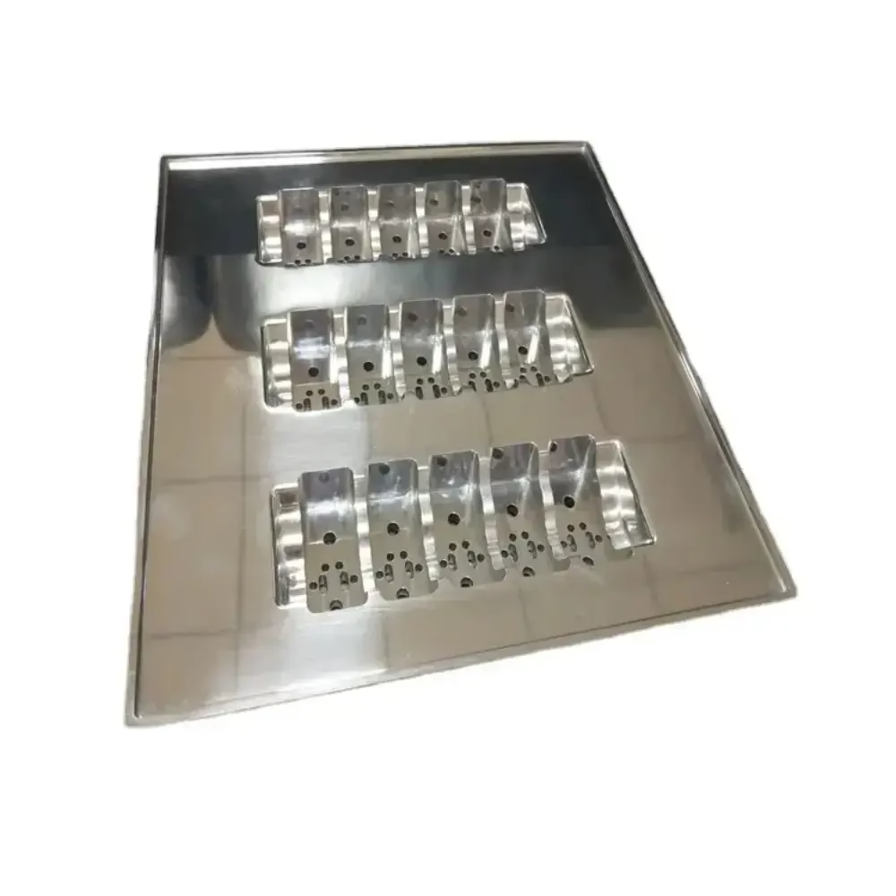
What 304 actually is, in metallurgical terms
Type 304 is an austenitic stainless steel with roughly 18% chromium and 8% nickel, which is why it is often written as 18/8. The chromium forms a passive oxide layer that re-forms within seconds after a tool breaks it. That layer is the whole point of the alloy: it gives corrosion resistance in food, water, and mildly acidic environments without any coating.
The catch is the crystal structure. Austenite is face-centered cubic, which means it has many slip systems. Instead of shearing off cleanly like a ferritic or pearlitic steel, the material deforms and hardens underneath the tool. This is not a defect. It is the reason 304 fights back on the machine.
The practical consequence is a hardened skin. Once a dull insert rubs the surface, the top 0.05–0.15 mm can climb from 180 HB toward 300 HB or higher. The next pass is cutting work-hardened metal, not annealed stock. Depth of cut has to stay above that layer, which is why 0.2 mm finishing passes on 304 usually burn the tool.
There is also a thermal side. 304 conducts heat poorly, around 16 W/m·K at room temperature. The heat generated at the shear zone has nowhere to go, so it concentrates in the chip and the insert edge. Tool life on 304 is usually set by edge temperature, not by mechanical load.
- 1Chromium oxide layerRe-forms in seconds after cutting; no coating required for corrosion resistance
- 2Face-centered cubic latticeMany slip systems, so the material work-hardens instead of shearing cleanly
- 3Low thermal conductivityHeat stays at the cutting edge and shortens insert life
Why 304 work-hardens at the tool tip
Work hardening is the reason 304 stainless steel CNC processing has a reputation. As the tool pushes into the material, dislocations pile up around the shear plane and the local hardness rises. The effect is strongest where the tool rubs instead of cuts: a small nose radius, a worn edge, or a feed rate that is too low to keep the tool engaged.
Feed rate matters more than most shops admit. A 0.08 mm/rev feed on a 12 mm carbide end mill keeps the edge rubbing and builds a hard layer. Pushing to 0.12–0.20 mm/rev for roughing keeps the chip thick enough to carry heat away and keeps the cutting edge below the hardened zone on the next pass.
Radial engagement is the other half. Full-width slotting in 304 loads the tool through a 180° arc and traps chips. Trochoidal or dynamic paths that hold radial engagement at 8–12% of cutter diameter spread the load and let coolant reach the cut. Cycle time rises, tool life rises more.
Rigidity is not optional. Any deflection means the edge rubs, the surface hardens, and the following tooth cuts into that hardened layer. Short tool holders, minimal overhang, and a rigid setup do more for 304 than a change of insert grade.
- 1Keep feed per tooth up0.12–0.20 mm/rev roughing; too light a feed rubs and hardens
- 2Limit radial engagement8–12% of cutter diameter with trochoidal paths
- 3Minimize overhangDeflection is what starts the hardening cycle
Cutting parameters that hold ±0.005 mm
The tolerance itself is not the hard part. ±0.005 mm (±0.0002 in) is achievable on 304 with the right machine, tool, and thermal control. What breaks it is heat. A 304 part grows 16 μm per 100 mm for every 10 °C of temperature rise, so a spindle that has been running for two hours is not the same machine it was at 8 a.m.
For turning, coated carbide inserts at 120–180 m/min with 0.15–0.25 mm/rev feed and 0.5–2.0 mm depth of cut cover most 304 work. Below 100 m/min the built-up edge starts to smear the finish. Above 200 m/min edge temperature climbs fast and insert life drops.
For milling with solid carbide, surface speed usually lands between 60 and 120 m/min. A 10 mm end mill at 3,000 rpm gives roughly 94 m/min, which is a safe starting point. Feed per tooth of 0.05–0.08 mm for finishing, 0.10–0.15 mm for roughing.
Finishing passes should be 0.2–0.5 mm radial and no more than 0.3 mm axial on thin walls. Below 0.1 mm the edge rubs rather than cuts, and Ra climbs instead of falling. Coolant should be flood or high-pressure through-tool, not mist. 304 needs the heat removed, not just lubricated.
- 1Turning120–180 m/min, 0.15–0.25 mm/rev, 0.5–2.0 mm DOC
- 2Milling60–120 m/min, 0.05–0.08 mm/tooth finishing
- 3Finishing pass0.2–0.5 mm radial, ≤0.3 mm axial on thin walls
Fixturing and 5-axis work on thin 304 parts
Thin-wall 304 parts are where the process earns its keep. A wall under 1.5 mm deflects under clamping force long before the tool touches it. Soft jaws machined to the part profile, or a low-melt fixturing compound, spread the load and let the wall relax after unclamping.
Five-axis machining removes the second and third setups that used to introduce stacked tolerance. On a part with features on four faces, one five-axis setup holds ±0.005 mm far more reliably than three three-axis operations, because the datum never moves. We run 16 simultaneous 5-axis machining centers, with a Ø400 mm rotary table for smaller work and travel up to 4,000 × 400 × 150 mm for long parts.
Chip evacuation is a real constraint in 304. The chips are stringy and work-hardened, and they pack into pockets. Through-spindle coolant at 70 bar or higher breaks them, and programming a peck-free continuous path avoids the dwell that lets chips weld to the cutter.
For parts that will be welded or heat treated after machining, plan the sequence. Welding 304 pulls distortion into the part, so critical bores should be machined after welding, or the part should be stress-relieved first.
- 1Soft jaws or low-melt fixturingReduces clamp-induced distortion on walls under 1.5 mm
- 2One five-axis setupRemoves stacked tolerance from multiple three-axis operations
- 3Through-spindle coolant70 bar or higher to break stringy 304 chips
Where 304 CNC processing stops making sense
304 is not always the right answer. When a part sees chlorides above roughly 200 ppm, pitting resistance becomes the controlling property and 316 or 316L is the correct call, even though it machines 20% slower. The cost of a failed part is higher than the cost of the extra cycle time.
When the geometry is a simple turned bushing in high volume, 303 is the better choice. The added sulfur improves chip breaking and raises machinability by roughly 40%. It cannot be welded, and it corrodes faster in marine air, so the trade only works for dry, indoor service.
When the part is mostly a surface, not a structure, 304 may be over-specified. A decorative cover plate inside a dry enclosure does not need 18/8. 430 or even painted carbon steel will do the same job for less money.
Finally, geometry sets the limit more often than material does. A pocket 4 mm deep and 3 mm wide in 304 needs a long, slender tool that will deflect. In that case the fix is a design change, not a different cutter.
- 1Chlorides above 200 ppmMove to 316 or 316L
- 2High-volume turned parts303 machines faster if welding is not required
- 3Deep narrow pocketsRedesign before changing tooling
304 vs 303 vs 316: which alloy for which part
Pick the alloy before you pick the process. Machinability and corrosion resistance trade against each other.
| Grade | Machinability | Best for | Avoid when |
|---|---|---|---|
| 304 | Baseline (100%) | Food, water, general corrosion | Heavy chip volume, high-speed production |
| 303 | About 140% of 304 | Screw machine parts, bushings, fittings | Welding, marine chloride exposure |
| 316 / 316L | About 80% of 304 | Chlorides, medical, marine | Cost-sensitive non-corrosive parts |
| 17-4PH | About 70% of 304 | High-strength shafts, valves | Maximum corrosion resistance needed |
| 430 | About 120% of 304 | Decorative, mild indoor service | Any wet or acidic environment |
The short version
If the part needs corrosion resistance and will be welded, stay with 304 and accept the slower cutting parameters. If it is a dry, high-volume turned part, switch to 303 and cut the cycle time. If chlorides are present, pay for 316.
Questions engineers ask about 304
Can 304 be machined to Ra 0.2–0.8 μm?
Yes, but it takes a dedicated finishing pass with a sharp, coated insert and a rigid setup. The usual failure mode is a finishing pass that is too light: below 0.1 mm radial engagement the edge rubs, work-hardens the surface, and Ra gets worse instead of better.
For very fine finishes on 304, a slow finishing pass at 0.2–0.3 mm radial with high-pressure coolant gets to Ra 0.2–0.8 μm. Polishing or bead blasting can follow if the drawing calls for it.
Does 304 need post-machining passivation?
Machining leaves free iron and embedded tool material on the surface, which can rust even though the bulk alloy will not. Passivation in citric or nitric acid removes that contamination and lets the chromium oxide layer rebuild evenly.
It is not required for every part. For food-contact, medical, or marine service, it is standard practice. For an internal bracket in a dry enclosure, it usually is not worth the extra step.
Why do my 304 tools fail after 20 minutes?
Edge temperature, almost always. 304 conducts heat poorly, so the insert tip absorbs most of the cutting energy. If surface speed is above 180 m/min for turning or 120 m/min for milling, insert life drops quickly.
Check coolant delivery next. Mist cooling does not remove enough heat from 304. Flood or through-tool coolant at pressure is what keeps the edge alive.
Is 304 suitable for thin-wall parts?
It can be, but walls below 1.5 mm need care. Clamping force alone can distort the part before the tool starts cutting. Soft jaws machined to the profile, or low-melt fixturing compound, keep the wall supported.
Light finishing passes of 0.2–0.3 mm radial and a sharp tool also help. If the design allows, adding a temporary rib that is removed in a later operation is a reliable way to hold thin 304 walls.
How does 304 compare with 316 for machining cost?
316 machines about 20% slower than 304 at the same tool life, mainly because of higher nickel and molybdenum content. It also work-hardens a little faster under light feeds.
The cost difference is small compared with the cost of a corrosion failure. If the service environment has chlorides, 316 is usually the cheaper decision over the life of the part.
Can 304 parts be welded after CNC processing?
Yes, but plan the machining sequence. Welding pulls distortion into the part near the weld, so any tight bore or flat face close to a weld should be machined after welding, or the assembly should be stress-relieved before final machining.
Austenitic 304 welds well with 308L filler. It does not respond to hardening heat treatment, so strength comes from cold work or from choosing a different grade.
Send us the 304 drawing
Upload a STEP file and we will return a quotation with a free DFM analysis within 12 hours. No minimum order quantity, from one prototype to 10,000+ part runs.
12-hour quote±0.005 mm tolerance100% inspection
More from GreatLight
We publish setup notes, tooling trials and inspection data from the factory floor.











