
Tool CNC Machine: 7 Essential Mistakes to Avoid Costly Rework
This page is for engineers and buyers who already have a part in production and something is drifting, chipping, or failing inspection. We walk through the seven tool CNC machine mistakes we see most often, what each one looks like on the shop floor, and how to correct it before the next run.
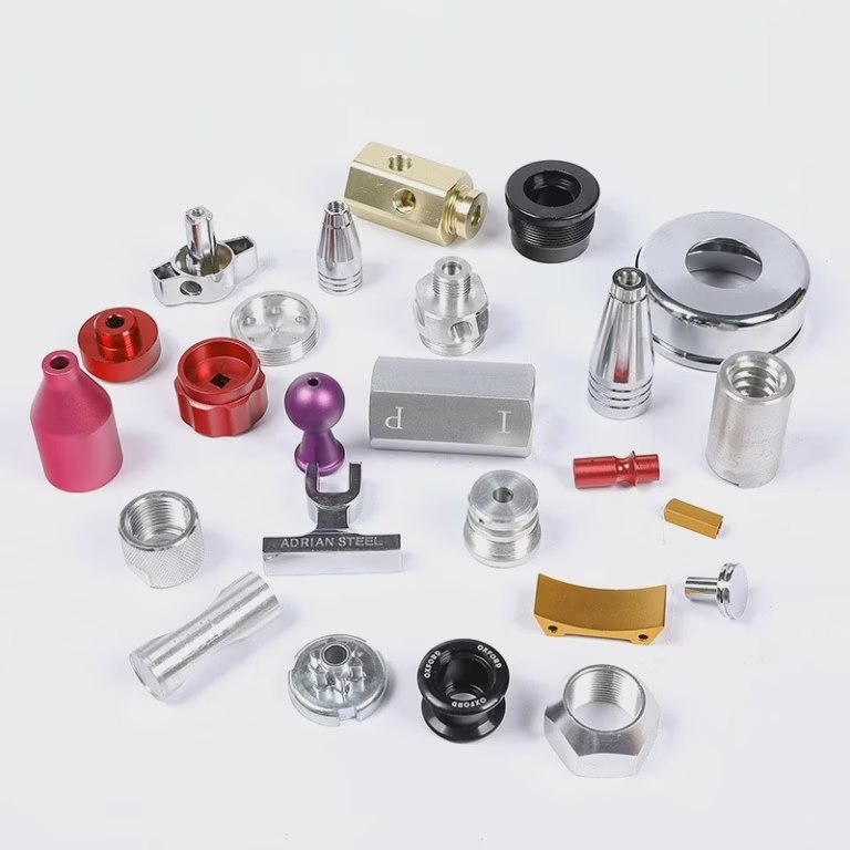
Seven tool CNC machine mistakes at a glance
Match your symptom to the likely cause before you change any cutting data.
| Symptom | Likely cause | What to do |
|---|---|---|
| Parts drift mid-run | Thermal growth not measured | Run warm-up cycle, log spindle temperature |
| Chatter on thin walls | Weak fixturing, no support | Add soft jaws or a tailstock, reduce radial depth |
| Short tool life | Speed and feed from catalog only | Tune feed per tooth to chip load range |
| Ra worse than drawing | Stepover too wide, dull insert | Cut stepover to 5–8% of tool Ø, replace insert |
| Cracks after machining | Material not normalized | Require annealed stock, check mill cert |
| First article passes, run fails | No in-process check | Add probe checks every 10–20 parts |
| Quote creep on complex parts | DFM skipped before toolpath | Free DFM review before CAM starts |
Spec sheets, material, and DFM before the spindle turns
The first tool CNC machine mistake is trusting a spec sheet instead of the machine in front of you. A brochure may claim ±0.001 mm, but thermal displacement, spindle runout, and worn ball screws set the real limit. Ask for a first article inspection report and a CMM report from a similar job. If the supplier cannot show one, the number is marketing, not capability.
Material choice is the second trap. Picking stock only on price ignores machinability, heat treatment state, and residual stress. A 7075 block that was never stress-relieved can move after the first roughing pass, and titanium that was not annealed may crack at the corner radius. We ask for the mill certificate and the heat lot before programming anything.
The third mistake is skipping design for manufacturability. Deep pockets with sharp internal corners, threads that end in a blind hole with no runout, and tolerances tighter than the function needs all raise cycle time and scrap risk. A DFM review before CAM catches these. At GreatLight we return a free DFM analysis within 12 hours, which is far cheaper than a rebuilt toolpath.
None of these three require a new machine. They require someone to read the drawing, the stock cert, and the inspection data before the first cut. When that step is skipped, the shop spends the next week chasing dimensions that were never going to hold.
Workholding and toolpath choices that decide surface finish
Bad fixturing is the fourth mistake and the hardest to see in a quote. A part held on three points with a light clamp will vibrate. The vibration shows up as chatter marks, out-of-round bores, and a finish of Ra 3.2 μm when the drawing calls for Ra 0.8–1.6 μm. Soft jaws machined to the part profile, a proper tailstock, or a vacuum plate usually fixes it.
Clamping force matters too. Over-tightening a thin aluminum wall distorts it during cutting, and the part springs back when unclamped. For a 6061 housing with 2 mm walls, we rough, relieve the clamps, then finish with light passes. That two-stage approach holds the wall flat within ±0.005 mm on the 16 simultaneous 5-axis centers we run.
The fifth mistake is copying a toolpath strategy from a different material. Catalog speeds and feeds assume ideal conditions. In practice you tune feed per tooth to the chip load the cutter can evacuate, then adjust radial and axial depth. On 17-4PH stainless we often drop surface speed and raise feed per tooth to keep the heat in the chip, not in the edge.
High-efficiency toolpaths with constant engagement extend tool life and hold finish. Trochoidal passes on a deep pocket keep radial engagement near 5–8% of tool Ø. The trade-off is longer cycle time and more CAM work. For a one-off prototype that is often not worth it; for a 10,000-part run it pays back within the first few hundred parts.
In-process inspection and partner selection
The sixth mistake is checking only the first and last part. Tools wear, chips build up, and coolant concentration drops over a shift. A bore that starts at 20.00 mm may be 20.03 mm by part 200. In-process probing every 10 to 20 parts catches the trend before it becomes scrap. That is cheaper than sorting a full batch after the fact.
We inspect raw material on arrival, monitor dimensions during the run, and do a final check before shipment. Critical features get CMM verification, and reports go out on request. With 127 high-precision CNC machines across three plants, we can route a job to the machine that fits the tolerance band instead of forcing one machine to cover everything.
The seventh mistake is treating the supplier as a vendor rather than a partner. A vendor quotes a drawing. A partner flags that the corner radius needs a 0.5 mm end mill, that the anodize will add 8–12 μm per surface, and that the thread callout should be class 2B instead of 3B. Those notes arrive before the first chip, not after.
Full-process integration matters here. When milling, turning, finishing, and inspection sit under one roof, the tolerance stack does not get handed off between companies. Parts ship in 3–5 days, and the historical late-delivery probability is below 2%. That is not a promise of a date; it is a track record you can ask us to explain.
How to correct these mistakes step by step
Work through the list in order. Fixing fixturing before you touch cutting data saves a full setup.
- 1Log the actual machine capabilityRun a warm-up cycle for 30–45 minutes, then cut a test coupon and measure it with a CMM. Record spindle temperature and ambient temperature at the same time. Use that data, not the brochure, as your tolerance baseline.
- 2Verify the material conditionCheck the mill certificate for heat lot and temper. For 7075, 4140, and Ti-6Al-4V, confirm stress relief or annealing before roughing. If the cert is missing, ask the supplier to re-certify or change the stock.
- 3Run a DFM review before CAMList every feature with a tolerance tighter than ±0.05 mm, every internal corner, and every thread depth. Flag anything a standard end mill cannot reach. Send the marked drawing to the shop and ask for cycle-time impact.
- 4Rebuild the workholdingMachine soft jaws to the part profile, add support under thin floors, and use light clamping with a two-stage rough and finish. For parts over 300 mm, add a tailstock or steady rest to control deflection.
- 5Tune the toolpath to chip loadStart at the cutter maker's feed per tooth, then adjust until chips are the right color and shape. On aluminum 6061, aim for Ra 0.8–1.6 μm with a stepover of 5–8% of tool Ø. On stainless, reduce surface speed and raise feed per tooth.
- 6Add in-process probingProbe a critical feature every 10–20 parts and log the reading. Set a warning band at 60% of the tolerance and a stop band at 80%. Replace inserts on a fixed count, not on feel.
- 7Close the loop with the partnerSend the inspection log back to the shop after each run. Ask what changed and what they would adjust next time. A partner who answers that question in writing is worth keeping.
Questions engineers ask about tool CNC machine mistakes
How do I know if a supplier can really hold ±0.005 mm?
Ask for a first article inspection report and a CMM report on a comparable part. Look for the measurement method, the ambient temperature, and the number of samples. A single caliper reading is not evidence.
Then ask which machine will run your job and what its travel and spindle are. A shop with 16 simultaneous 5-axis centers and 27 three-axis machines can match the machine to the tolerance instead of forcing one platform to cover everything.
Why does my part chatter even though the drawing is simple?
Chatter usually comes from the setup, not the geometry. Thin walls, long overhangs, and light clamping let the part move. Check the workholding first: soft jaws, support under floors, and a tailstock for long parts.
If the setup is solid, reduce radial engagement and check tool runout. A cutter with 0.02 mm runout will cut on one flute and leave a finish that looks like chatter.
When is high-efficiency toolpath worth the extra CAM time?
On runs above a few hundred parts, or when tool life is the bottleneck. Constant-engagement paths keep radial load steady, which reduces edge chipping and holds finish longer.
For a one-off prototype, conventional paths with a larger stepover are usually faster to program and good enough. The trade-off is real, so decide it per job, not per shop policy.
How often should I check dimensions during a production run?
Every 10–20 parts for a feature with a tight tolerance, and at every tool change. Log the reading so you can see a trend before it becomes a reject.
If the process is stable and the tool wear rate is known, you can stretch the interval. If the material lot changes, reset the interval to the shorter value until you have data on the new lot.
Does anodizing change the dimensions I should inspect?
Yes. Anodize builds 8–12 μm per surface depending on the process. For a bore, that means a smaller hole; for an outside diameter, a larger one. Mask critical fits or adjust the pre-plate dimension.
Tell the shop which surfaces are fits and which are cosmetic. That one note prevents a lot of rework after finishing.
What does a DFM review actually change?
It usually changes three things: corner radii, tolerance callouts, and thread depth. A change from a sharp corner to a 1 mm radius can cut cycle time and eliminate a second setup.
It can also change the material or the finish. If a hardcoat anodize is not needed for wear, a clear anodize may be enough. We return the review within 12 hours so the decision happens before CAM.
Send the drawing and the problem
We will return a quote and a free DFM analysis within 12 hours, and tell you which of these seven mistakes is most likely on your part.
12-hour quote100% inspectionNo minimum order
More machining notes
We publish setup notes, tooling trials and inspection data from the factory floor.











