
5 CNC Precision Tips to Avoid Costly Machining Errors
Most scrap on a precision job is decided before the spindle turns. This guide is for design engineers, procurement engineers and hardware teams who release drawings to machine shops. Read it to judge which tolerances, features and inspection steps actually drive cnc precision, and which ones only add cost.
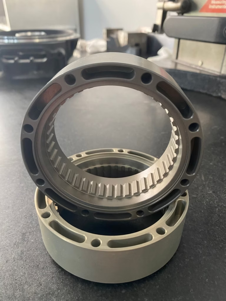
Where Costly Machining Errors Actually Come From
Five tips, in the order they affect your part cost.
Match the Alloy to the Machine, Not the Other Way Around
A drawing that says aluminum does not tell the shop much. 6061-T6 cuts clean and holds thin walls well. 7075 is stronger but more prone to stress movement after roughing. Ti-6Al-4V and Inconel push cutting temperature up and tool life down, so the same cutter that works on 6061 may chatter in titanium. When we program a job, alloy grade decides feed, speed, depth of cut, coolant strategy and the rough, semi-finish, finish sequence.
The common failure is a tight tolerance on a difficult material with no regard for how that material moves. A ±0.005 mm callout on a thin titanium rib is a warpage and chatter risk, not a precision requirement. On thin features we often ask whether a slightly wider tolerance would still meet the function. If yes, the part usually gets cheaper and more consistent.
Send the specific grade, not a family name. Plastics behave the same way: POM and PEEK machine cleanly, while soft PP and HDPE deflect under clamping and need light passes. Wall thickness, bosses and pockets all shift how the material reacts. Tell us the application and the thermal or mechanical load, and the toolpath can be planned around it instead of corrected after the first article.
- 1Give the grade6061-T6, 7075, 17-4PH, TC4 (Ti-6Al-4V), PEEK, not just aluminum or stainless.
- 2Flag thin wallsAnything under 1 mm changes fixturing and pass strategy.
- 3State the loadStatic, thermal or fatigue duty decides how much tolerance you can give back.
Fix DFM Issues Before the Drawing Is Released
Deep pockets with sharp internal corners are the most expensive feature on many parts. A sharp corner needs a cutter with a small radius, which must run slower and deflects more, and the corner still cannot be cut square. Adding a corner radius equal to the tool radius usually removes a second operation and a polishing step.
Tool access decides cost more than tolerance does. A feature on a face the tool cannot reach needs a longer cutter, an angled setup or a different machine. On parts that fit our 4,000 mm maximum processing size we can often reach those faces in one five-axis setup instead of three. That is a real saving, but it has to be seen at quote time, not after the first article.
Thread depths, hole depth-to-diameter ratios and text size matter too. Laser marking needs a minimum character height of 1.5 mm, and a deep small hole needs a peck cycle that adds cycle time. None of these are errors on their own. Together they decide whether the part runs at the quoted cost or drifts above it.
- 1Add corner radiiMatch the radius to a standard cutter and drop the EDM step.
- 2Keep walls uniformSudden thickness changes pull heat and stress into one zone.
- 3Respect the toolIf no standard cutter reaches it, expect a custom setup.
- 4Size the textLaser engraving needs 1.5 mm minimum character height.
Surface Finish and Tolerance by Feature Type
Typical values we hold on production runs.
| Feature | Typical tolerance | Achievable finish |
|---|---|---|
| Milled face, rigid setup | ±0.005 mm | Ra 0.8–1.6 μm |
| Bored hole, single setup | ±0.005 mm | Ra 0.2–0.8 μm |
| Turned OD, stable stock | ±0.005 mm | Ra 0.8–1.6 μm |
| Thin wall under 1 mm | ±0.005 mm after stress relief | Ra 1.6–3.2 μm |
| Deep pocket, small corner | ±0.005 mm with corner radius | Ra 1.6–3.2 μm |
| As-machined cosmetic face | ±0.005 mm | Ra 1.6–3.2 μm |
Temperature and Vibration Move Metal More Than You Expect
Aluminum expands about 23 μm per meter per degree Celsius. A shop floor that swings 8 °C across a shift moves a 300 mm bore by a measurable amount before the cutter touches it. That is why we keep finishing cells temperature-stable and let rough stock cool before the finish pass. It is also why a first article measured on a warm part can read differently the next morning.
Vibration is the other silent error. A cutter with too much overhang, a part held on one small contact patch, or a spindle running at a harmonic of the part will leave chatter that looks like a finish problem but is really a stiffness problem. Chatter also wears the tool edge, so hole size drifts across a run. Shortening overhang and adding support usually fixes it faster than slowing the feed.
Both effects are worse on long parts. On the 4,000 × 400 × 150 mm travel machines we use for long extrusions and rails, thermal growth over the length is a real planning item. We measure after the part stabilizes, not straight off the table.
- 1Let it coolRough, cool, then finish on tight-tolerance faces.
- 2Shorten overhangRigidity beats a slower feed for chatter control.
- 3Measure stableInspect after thermal soak, not at tool exit.
Workholding Sets the Real Precision Limit
The machine is rarely the weak point. The setup is. A part clamped on a small pad will deflect under cutting force, spring back after the pass, and measure oversize or undersize depending on where the load was. Soft jaws machined to the part profile, vacuum plates for thin panels and dedicated fixtures for repeat runs all remove that variable.
For a single prototype, a simple vise and parallels may be enough. For a run of 500, a fixture that locates on a datum every cycle pays back within a few parts. We machine soft jaws on the machine that will run the job, so the jaw geometry matches the spindle, not a separate setup.
Five-axis work changes the calculation. Rotary work on a Ø400 mm table lets us reach five faces without re-clamping, which removes stack-up from multiple setups. It also means the part sees a different stiffness in each orientation, so we plan the sequence to finish the tightest faces in the most rigid position.
- 1One datumLocate every operation from the same reference.
- 2Support thin partsVacuum or conformal support stops deflection mid-cut.
- 3Fewer setupsFive-axis access cuts stack-up error on complex parts.
Inspect During the Run, Not Only at the End
Final inspection tells you whether the last part was good. In-process monitoring tells you whether the next one will be. We check raw material on arrival, monitor dimensions during the run and do a full final inspection before shipment, with reports on request. On a long run this catches tool wear before it turns into a batch of out-of-tolerance bores.
Tool wear is the usual drift source. A carbide end mill that starts on size will not stay there for 2,000 parts. Measuring a sample at fixed intervals and offsetting the tool keeps the mean centered. On materials like 17-4PH or Inconel the wear rate is higher, so the interval is shorter.
First-article inspection matters most on new geometry. We cut the part, measure it, and compare against the model before the run is released. If the drawing has an ambiguous callout, this is where it surfaces. Finding it on part one is cheap. Finding it on part 400 is not.
- 1Set the intervalSample more often on hard alloys and long runs.
- 2Offset earlyCompensate for wear before the part drifts out.
- 3Approve the first articleResolve drawing questions on part one.
Questions Engineers Ask About CNC Precision
How tight a tolerance can you actually hold?
We hold ±0.005 mm (±0.0002 in) on features that the process supports: rigid setups, stable materials, accessible faces.
The tolerance is only one input. A thin wall, a deep pocket or a difficult alloy can make a ±0.005 mm callout expensive or unreliable, and we will say so at quote time rather than after the run.
What finish should I specify?
Ra 0.8–1.6 μm covers most sealing faces, bearing seats and mating surfaces. Ra 0.2–0.8 μm is for fine sealing or optical contact and adds a finishing step.
Ra 1.6–3.2 μm is normal as-machined and is usually enough for brackets, covers and housings.
Do you need a 3D model or are 2D drawings enough?
A 3D model plus a 2D drawing for tolerances, finish and material is the cleanest package. The model defines geometry, the drawing defines acceptance.
If you only have a drawing, we can still quote, but we will flag any feature that is ambiguous before cutting.
Can you work from a prototype to a production run?
Yes. There is no minimum order quantity, so one prototype and a 10,000+ part run are both normal for us.
The fixture and inspection plan change between those two, but the drawing and the datum stay the same.
How do you handle confidential designs?
Uploads are secure and confidential, and we can sign an NDA before you send files.
Access is limited to the engineers who need the data to quote and program the part.
Which certifications do you hold?
ISO 9001:2015, IATF 16949:2016, ISO 13485:2016 and ISO 27001:2022.
These cover general quality, automotive, medical device and information security scope respectively.
Send the Drawing and Get a DFM Review
Quotation and free DFM analysis within 12 hours. 127 high-precision CNC machines, ±0.005 mm tolerance and 100% inspection before shipment.
12-hour quoteFree DFM analysisNo MOQNDA on request









