
What Can You Make on a CNC Machine?
Short answer: any solid part you can describe as a 3D model and hold in a vise or fixture. The longer answer depends on axis count, material, and how tight the tolerances really are. This page walks through the part families, the geometry each machine type can reach, and the point where machining stops being the right process.
Part families that fit a CNC machine
The honest answer to what you can make on a CNC machine starts with one test: can the part be held rigidly while a spinning cutter reaches every surface? If yes, it is machinable. That covers engine brackets, gearbox housings, surgical handles, robot joint links, enclosure bezels, heat sinks, valve bodies, and fixture plates. If a feature sits inside a closed cavity with no tool entry, no cutter will reach it. That is a design problem, not a machine problem.
Machined parts usually fall into three size bands. Compact work such as connectors, small gears, and implant trials sits under 500 mm. Mid-size work like manifolds, motor housings, and chassis nodes runs from 500 mm to about 1,200 mm. Large structural parts such as aerospace ribs and gantry beams go up to 4,000 mm on our long-travel machines. Size drives machine choice more than complexity does.
Batch size matters less than people expect. A single prototype and a 10,000-part run use the same cutting physics. What changes is the fixture, the cycle time, and whether a second operation is worth building a dedicated soft jaw for. There is no minimum order quantity here, so a one-off bracket and a production run are both normal jobs.
The parts that machine badly are usually thin, flexible, or highly reflective. A 0.5 mm wall in aluminium will chatter unless it is supported. Copper and pure aluminium gum up cutters without the right coolant and geometry. These parts are still machinable, but expect slower cycle times and more scrap risk.
- 1Prismatic solidsBlocks, plates, housings and brackets with pockets and holes on accessible faces.
- 2Rotational partsShafts, bushings, fittings and threaded bodies turned on a lathe or mill-turn center.
- 3Sculpted surfacesCavities, blades and organic shapes that need simultaneous multi-axis motion.
- 4Thin-wall partsMachinable, but they need support, light passes and a planned stress-relief step.
How axis count changes what you can make
A 3-axis machine moves the cutter in X, Y and Z while the part stays still. This handles any part where all features face one direction: plates, brackets, covers, simple housings. It is the fastest and cheapest route when the geometry allows it. If your part needs a hole on the side face, you either add a second setup or move up an axis. Each extra setup costs time and adds a small positional error between operations.
A 4-axis machine adds a rotary table, usually turning around the X or Y axis. That lets the cutter reach four sides of a part without re-clamping. Shafts with cross-drilled holes, cylindrical housings with slots, and long parts with features along the length all fit here. Our rotary tables are Ø400 mm, so parts up to that diameter can be indexed in one program. The fifth face still needs a flip.
A 5-axis machine adds a second rotary axis, which tilts the tool or the part. This is what lets a cutter follow a contoured surface at the correct angle instead of dragging the tip. Impellers, turbine blades, deep pockets with undercuts, and parts with compound angles live here. Simultaneous 5-axis also shortens cycle time on complex parts because the tool stays engaged instead of lifting and repositioning.
The trade-off is real. Five-axis programming takes longer, and not every part benefits. A flat plate with four holes does not get better on a 5-axis machine. It gets slower and more expensive. The rule we use: if the part has features on more than three faces, or a surface that cannot be reached from a single tool direction, 5-axis earns its cost. Otherwise, stay on 3-axis and spend the savings on finishing.
- 13-axisOne direction of features. Plates, covers, simple brackets. Lowest cost per part.
- 24-axisFour faces in one setup. Shafts, slotted tubes, cylindrical housings.
- 35-axisContoured and compound-angle geometry. Impellers, blades, deep cavities.
- 4Mill-turnRotational and prismatic features in one machine. Cuts handling between operations.
What materials can a CNC machine cut?
Aluminium is the default for prototypes and many production parts. Grades 6061 and 7075 cut cleanly, hold tight tolerances, and take anodizing well. 2024 is stronger but harder to weld. 6061-T6 is the safe pick when you need a balance of strength, finish and cost. For hot or highly loaded parts, 7075 gives more strength at a small premium in tool wear.
Stainless steel grades 303, 304, 316 and 17-4PH cover most corrosion-resistant work. 303 machines freely and is the choice for high-volume turned parts. 316L is the standard for medical and food-contact parts. 17-4PH gives high strength after heat treatment, which matters for shafts and valves. Expect slower feeds and more tool wear than aluminium.
Steel grades 1018, 1045, 4130 and 4140 cover structural and wear parts. 4140 is common for shafts and gears that need through-hardening. Titanium TC4 (Ti-6Al-4V) and Inconel are machinable but costly: they hold heat at the cutting edge, so speeds drop and tool life shortens. These are the materials where a wrong feed rate shows up immediately in the surface finish.
Plastics behave differently. POM and PA machine cleanly and hold tolerance. PEEK is dimensionally stable at high temperature but abrasive. ABS and PC are soft and prone to melting if the cutter dwells. Carbon fibre is abrasive in a different way: it wears tools fast and needs dust extraction. In every case, the material dictates the cutter geometry, the coolant, and the finishing pass more than the machine does.
- 1Aluminium6061, 7075, 2024, 5052, 6082. Fast cutting, good finish, easy anodizing.
- 2Stainless303, 304, 316L, 17-4PH. Corrosion resistance, slower feeds, more tool wear.
- 3Steel and titanium1045, 4140, TC4, Inconel. High strength, low speeds, tight process control.
- 4PlasticsPOM, PEEK, PC, ABS, carbon fibre. Light cuts, sharp tools, dust control.
What tolerance and finish you can actually hold
Our standard machining tolerance is ±0.005 mm on critical features. That is not a blanket number for every dimension on a drawing. It applies to features the process can control: bores, mating faces, and datums held in a single setup. A dimension that spans two setups will carry the positional error between them, so it is worth designing around one-setup datums where you can.
Surface finish runs from Ra 1.6–3.2 μm as machined, down to Ra 0.8–1.6 μm with a controlled finishing pass, and Ra 0.2–0.8 μm where a fine finish is specified. Finer finish costs cycle time because it means lighter passes and sometimes a separate finishing tool. If your part only needs a sealing face at Ra 0.8 μm and the rest can stay as machined, say so on the drawing. It saves money.
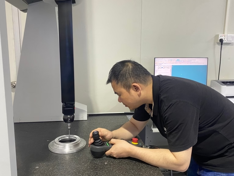
Inspection is where tolerance claims get verified. We check raw material on receipt, monitor dimensions during cutting, and inspect 100% of parts before shipment. Reports are available on request. For a first article, ask for the dimensional report before you commit to a production run. It tells you whether the process is capable on your specific geometry, not just on a general tolerance chart.
The parts that fail tolerance checks are rarely the complex ones. They are the ones with an ambiguous datum, a thin wall that moves after clamping, or a callout that conflicts with the material. Fix the drawing before the first cut. A DFM review within 12 hours of quoting usually catches these before metal is committed.
- 1Standard±0.005 mm on controlled features held in one setup.
- 2As machinedRa 1.6–3.2 μm. Fine for non-sealing, non-sliding surfaces.
- 3Fine finishRa 0.2–0.8 μm where a sealing or bearing face needs it.
- 4Inspection100% before shipment, with dimensional reports on request.
Parts by industry: what each sector actually orders
Automotive and EV work centres on engine hardware, transmission components, chassis brackets and battery housing parts. The parts are usually aluminium or steel, mid-size, and need consistent dimensions across thousands of units. IATF 16949:2016 covers this work. Tolerances tighten around sealing faces and bearing bores, while cosmetic surfaces matter less than fit.
Aerospace parts are structural ribs, brackets, housings and fittings in aluminium or titanium. The driver is strength-to-weight, which pushes toward thin walls, pocketed webs and sculpted surfaces. These parts often need 5-axis work and Ra 0.8–1.6 μm on mating faces. Documentation and traceability matter as much as the cut itself.
Medical devices include surgical instrument handles, implant trials, bone plates and housing components in 316L stainless or titanium. ISO 13485:2016 applies. The parts are small, the tolerances are tight, and the surface finish affects cleanability. Burr-free edges are a design requirement, not a nice-to-have, because a burr traps contamination.
Robotics and electronics fill in the rest. Robot joint links, end-effector mounts and gearbox housings need stiffness and repeatable bore positions. Electronics enclosures, heat sinks and connector shells need accurate cutouts and clean anodized finishes. Both categories tend to start as prototypes and move to production once the design stops changing.
- 1Automotive and EVEngine hardware, brackets, housings. IATF 16949:2016.
- 2AerospaceRibs, brackets, fittings. Light weight, tight mating faces.
- 3MedicalInstrument handles, plates, trials in 316L or titanium. ISO 13485:2016.
- 4Robotics and electronicsJoint links, mounts, enclosures. Stiffness and accurate cutouts.
Which machine type fits which part
Use this as a first filter. If the part fits more than one row, start with the simplest machine that reaches every feature.
| Part type | Typical machine | Why | Watch out for |
|---|---|---|---|
| Flat plate with holes and pockets | 3-axis | All features reachable from one direction | Extra setups if holes sit on side faces |
| Shaft with cross-drilled holes | 4-axis | Rotary table indexes the part without re-clamping | Still needs a flip for the fifth face |
| Cylindrical housing with slots | 4-axis | Features wrap around the axis in one program | Rotary table limited to Ø400 mm |
| Impeller or blade | 5-axis | Cutter follows the contoured surface at the right angle | Programming time is higher |
| Part with undercuts and deep cavities | 5-axis | Tilting tool reaches geometry a straight cutter cannot | Needs longer reach tooling |
| Prismatic plus turned features | Mill-turn | Both feature types in one machine | Not economical for very simple parts |
| Part over 1,200 mm long | Long-travel 3-axis | Travel up to 4,000 × 400 × 150 mm | Requires large fixturing and handling |
When CNC machining is the right call
If your part is a solid, rigid shape with features a cutter can reach, machine it. If it is a hollow shell with internal channels or a thin-walled part in high volume, casting or 3D printing will usually cost less. For prototypes and low-to-mid volume in metal, machining wins on tolerance and material choice.
Frequently asked questions
Can a CNC machine make a part with internal channels?
Only if a cutter can enter from an open face. Straight drilled cross-holes are fine. Curved internal channels inside a solid block are not reachable by a spinning tool.
For those geometries, 3D printing or casting builds the channel into the part, and machining then cleans up the critical faces.
What is the largest part you can machine?
Our maximum processing size is 4,000 mm, with long-travel machines rated at 4,000 × 400 × 150 mm. Mid-size machines cover 750 × 1,150 × 550 mm and 600 × 600 × 600 mm.
Large parts need fixturing that keeps the part rigid across the full length. Long thin parts deflect, so support points are planned at quoting.
How tight a tolerance can I specify?
The standard is ±0.005 mm on features controlled in a single setup. Tighter callouts are possible on specific features, but they add cost and usually need a dedicated inspection step.
Specify tight tolerance only where the function needs it. A blanket tight tolerance across a drawing raises price without improving the part.
Is there a minimum order quantity?
No. We run from one prototype to 10,000+ part runs. Quotation and free DFM analysis come back within 12 hours, and production can start within 24 hours.
Parts typically ship in 3–5 days once cutting begins. Volume pricing applies to repeat runs, not to the first prototype.
Can you machine parts from titanium and Inconel?
Yes. We machine TA1, TA2, TC4 (Ti-6Al-4V), Inconel and magnesium grades AZ31B and AZ91D, alongside aluminium, stainless and steel.
These materials cut slowly because heat stays at the tool edge. Expect longer cycle times and a surface finish that depends heavily on the chosen feed and coolant.
What finishes can be applied after machining?
Anodizing in clear, colour, hardcoat and conductive types; electroless nickel, zinc, silver and gold plating; powder coating and black oxide; bead blasting, tumbling, brushing and polishing.
Laser marking and engraving are also available, with a minimum character height of 1.5 mm for legibility.
Send your part and get a straight answer
Upload a STEP file and we will tell you whether it machines cleanly, which axis count it needs, and where the cost sits. Quotation and DFM feedback within 12 hours.
12-hour quote100% inspectionNo MOQNDA on request
More from the shop floor
We publish setup notes, tooling trials and inspection data from the factory floor.











