
What Can You Make With a Metal CNC Machine?
Ask what can you make with a metal CNC machine and the honest answer starts with how the part is held and where the cutting force goes. This page groups the work into seven part classes, shows the tolerance and size limits behind each one, and explains when a cut part stops making sense. Written for design engineers and buyers who need to pick a process before they release a drawing.
In this article
- 1
- 2
- 3
- 4
- 5
- 6
- 7
- 8
- 9
What decides whether a part can be machined
Prismatic housings and enclosures
The biggest single category on any metal CNC machine is the prismatic housing: a block of aluminum or steel with pockets, bosses, bores, and a bolt pattern on several faces. Electronics enclosures, gearbox bodies, pump housings, and motor mounts all live here. These parts share one trait: most features are reachable from three to six orthogonal directions, so 3-axis and 4-axis work handles them well.
Wall thickness is where designs fail. In 6061-T6, a 1.5 mm wall at 60 mm tall will ring during roughing. Bump to 2.5 mm or add a rib and the same part cuts clean. For 304 stainless, keep unsupported walls at 2 mm or more. A wall that is 10× thinner than its height is the practical warning line.
Pocket depth matters as much as wall thickness. A cutter needs to reach the floor without rubbing the side wall on the way down. A 6 mm end mill in a 40 mm deep pocket has a length-to-diameter ratio near 7, and it will deflect. Either open the corner radius, split the pocket into two depths, or accept a coarser floor finish.
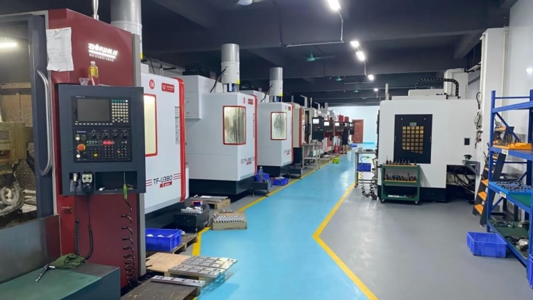
A 750 × 1,150 × 550 mm travel machine covers most enclosure work in one setup. Larger frames, up to 4,000 mm, are cut on our gantry-sized centers with the part flipped once and re-datumed from a ground reference face.
- 1Good fitRectangular bodies with orthogonal features and 2 mm+ walls.
- 2Needs redesignPockets deeper than 5× the tool diameter with sharp internal corners.
Shafts, pins, and turned parts
Anything that is mostly a surface of revolution goes to a lathe or a mill-turn center. Shafts, spindles, valve stems, bushings, threaded studs, and hydraulic fittings are the classic examples. Turning holds diameter and roundness tightly because the part spins against a fixed tool, so a Ø20 mm journal at ±0.005 mm is routine rather than special.
Concentricity is the feature that separates a good turned part from a scrap one. If two bearing journals must run within 0.01 mm TIR of each other, cut them in the same chucking or use a mill-turn center that can also drill the cross holes without releasing the part. Every re-chucking adds runout.
Threads and seal faces are the second risk area. A 1/4 NPT port needs a controlled taper and a clean crest; a damaged thread leaks. We cut threads with full-profile inserts and gauge them, rather than trusting the program alone.
Length-to-diameter ratio sets the boundary. Beyond about 6:1, a shaft needs a tailstock or a steady rest. Beyond 10:1, deflection and chatter become the dominant cost. At that point, grinding after turning is often cheaper than chasing the tolerance on the lathe.
- 1Good fitParts with one dominant axis and features within 6:1 length-to-diameter.
- 2Not idealVery long slender shafts; consider turning plus cylindrical grinding.
Complex 5-axis geometry
The 5-axis class covers parts that cannot be reached from three directions: impellers, turbine blades, dental and orthopedic implants, contoured mold inserts, and thin curved brackets for aerospace. Here the tool tilts to stay normal to the surface, which keeps the cutter engaged and lets a short, stiff tool do the work.
The gain is not only geometric. Short tools cut faster and leave a better finish, so a contoured surface can come off the machine at Ra 0.8–1.6 μm instead of needing hand polishing. On a titanium impeller, that difference is most of the cycle time.
The cost is programming and setup. A 5-axis toolpath must be verified for collision across the full rotary travel, and the fixture has to expose the part without blocking the tilt. We use 16 simultaneous 5-axis centers with a Ø400 mm rotary table for this class.
Know when 5-axis is overkill. A part with features on four flat faces is usually cheaper on a 4-axis mill with a trunnion. Reserve 5-axis for true free-form surfaces or for parts where one setup removes three fixtures.
- 1Good fitFree-form surfaces, deep undercuts, and parts that need one-setup accuracy.
- 2OverkillFlat-faced parts with simple holes; 3-axis or 4-axis costs less.
Prototypes, fixtures, and tooling
Metal CNC work is not only end-use parts. It is also the tooling that makes other processes possible: injection mold cores and cavities, die-casting inserts, stamping dies, weld fixtures, go/no-go gauges, and inspection nests. These parts are usually one-offs or low quantity, so setup time dominates.
For mold and die work, the material is often pre-hardened or hardened steel, and the cutting strategy changes. Hard milling at 45–62 HRC uses small radial engagement, high spindle speed, and light depth of cut. A 6 mm carbide ball tool taking 0.3 mm radial stepover is normal here, not a mistake.
Fixtures have their own rule: they must be stiffer than the part they hold. A soft fixture lets the part move during cutting, and the measured dimension drifts. We cut fixture plates from 7075 or 4140 and pin them to a sub-plate so the datum is repeatable across batches.
This class also covers prototype runs before hard tooling exists. A 5-axis machined aluminum housing can prove the design in days, while the die-cast version is still being quoted.
- 1Good fitOne-piece molds, weld fixtures, gauges, and pre-production prototypes.
- 2WatchHardened steel above 55 HRC needs dedicated tooling and slow feeds.
Thin-wall and lightened structures
Aerospace and robotics push toward parts that are mostly air: ribs, pockets, and pockets inside pockets. The machining challenge is that removing material changes the stiffness of the workpiece itself. The part that was rigid at the first cut is flexible by the last one.
The countermeasure is sequence. Rough with the part supported, leave 0.5 mm of stock, then semi-finish symmetrically so material comes off both sides at once. Finish cuts stay light, 0.2–0.3 mm radial, and the tool path alternates sides to keep the load balanced.
Support structures help. We sometimes leave tabs or a sacrificial web that holds a thin floor until the walls are done, then cut the tabs in a final pass. That single trick turns a chattering part into a stable one.
Material choice follows the same logic. 7075-T6 and titanium hold thin sections better than 6061 because of higher stiffness. Magnesium AZ31B cuts even faster, but it needs chip control and a strict no-water rule during cutting.
- 1Good fitRibbed brackets, lightweight housings, and lattice-like internal structures.
- 2Not idealWalls under 0.8 mm in aluminum; consider sheet metal or 3D printing instead.
Surface-critical and sealing parts
Some parts are defined less by their shape than by their surface. Valve bodies, manifolds, hydraulic blocks, vacuum chucks, and optical mounts all need faces that seal or slide. Here the machine must deliver a controlled surface finish, not just a dimension.
O-ring grooves are the tightest case. The groove width and depth must match the cord diameter, and the side walls must be smooth enough that the seal does not tear on assembly. A rough groove leaks even when the dimensions are in tolerance. We finish these grooves at Ra 0.8–1.6 μm and inspect the profile, not just the width.
Lapped and polished faces are the other end. A face that must hold vacuum at 10⁻⁶ mbar needs Ra 0.2–0.8 μm with no visible tool marks. That usually means fine milling followed by lapping on a separate operation, and it is worth specifying only when the function requires it.
Surface finish interacts with material. Aluminum smears at high cutting speed and leaves a built-up edge; stainless work-hardens if the tool rubs. Both problems show up as finish defects before they show up as dimensional errors.
- 1Good fitSeal grooves, lapped faces, and sliding surfaces with a defined Ra target.
- 2WatchCalling out Ra 0.2 μm on every face raises cost sharply for no functional gain.
When a metal CNC machine is the wrong answer
Milling and turning remove material, so they are wasteful by design. When a part is small, hollow, and needed in high volume, that waste becomes the dominant cost. A die-cast or injection-molded version of the same geometry can cost a fraction per piece once tooling is amortized.
Very thin sheet-like parts are the second mismatch. A 0.5 mm panel with a few holes is a laser or punch job. Cutting it from solid stock wastes material and the part will distort as residual stress releases.
Parts with internal channels that cannot be reached by a tool are the third. Conformal cooling channels inside a mold insert, or a lattice inside a bracket, need additive manufacturing. Sometimes the right answer is hybrid: print the complex core, then machine the critical faces.
Finally, there is a tolerance floor. Below roughly ±0.002 mm, conventional milling reaches its limit and grinding, lapping, or EDM takes over. Knowing where that line sits saves a redesign later.
- 1Choose casting or moldingHigh volume, small size, hollow geometry with uniform walls.
- 2Choose sheet metalFlat parts under 3 mm thick with mostly 2D features.
- 3Choose additiveInternal channels or lattices that no cutter can reach.
Which process fits which part
Use this as a first filter before you commit to a drawing.
| Part signature | Best process | Why | Watch out for |
|---|---|---|---|
| Block with pockets on 3–6 faces | 3-axis / 4-axis milling | Orthogonal features, easy fixturing | Walls under 2 mm chatter |
| Mostly cylindrical with cross holes | Mill-turn center | One chucking holds concentricity | Length-to-diameter over 6:1 |
| Free-form curved surface | 5-axis simultaneous | Short tool stays normal to surface | Collision checks add programming time |
| Seal groove or lapped face | Milling plus lapping | Finish is the function, not the shape | Blanket Ra 0.2 μm callouts |
| Ribbed lightweight bracket | 3-axis with support tabs | Sequence keeps the part rigid | Walls under 0.8 mm in aluminum |
| 50,000 identical small housings | Die casting | Tooling cost amortizes per piece | Machining still needed on seal faces |
| Internal conformal channels | Additive plus finish milling | No cutter can reach the channel | Critical faces still need machining |
The short version
If your part is a rigid prismatic body or a shaft in low to medium volume, a metal CNC machine is the right call and ±0.005 mm is reachable. If it is small, hollow, and needed in tens of thousands, tool up for casting or molding and machine only the critical faces. Between those two, let wall thickness and tool reach decide.
Questions engineers ask next
What is the smallest feature a metal CNC machine can cut?
A practical floor for milling is a 1 mm end mill, which cuts slots about 1.2 mm wide and 4 mm deep before deflection becomes a problem. Smaller tools exist, but they break easily and the feed rates drop sharply.
For holes, drilling down to Ø0.5 mm is possible in aluminum with a rigid setup. Below that, EDM or laser drilling is usually more reliable than a rotating cutter.
Can a metal CNC machine hold ±0.005 mm on every dimension?
No. That tolerance is a capability on a specific feature under specific conditions: rigid setup, stable material, temperature-controlled room, and a finishing pass with a sharp tool. Across a whole drawing, the achievable tolerance depends on the feature.
Bores and flat faces hold tight easily. Long unsupported walls, deep narrow pockets, and features far from the datum do not. Mark the two or three dimensions that matter and leave the rest at general tolerance.
How do I know if my part needs 5-axis machining?
Ask whether any feature is unreachable from three orthogonal directions, or whether one setup would replace three. Free-form surfaces and deep undercuts point to 5-axis.
If the part is flat-faced with simple holes, 3-axis or 4-axis will cost less and quote faster. Five-axis adds programming and verification time that only pays off on complex geometry.
Which metals are easy to machine, and which are difficult?
Aluminum 6061 and 2024, brass C36000, and 303 stainless cut cleanly and are the default for prototypes. They hold tolerances well and leave a good finish without special tooling.
Titanium Ti-6Al-4V, Inconel, and 17-4PH stainless are harder. They generate heat at the cutting edge, work-harden, and wear tools quickly. Expect slower cycle times, more tool changes, and a higher price per part.
How does part size affect what can be machined?
Our largest travel is 4,000 × 400 × 150 mm on a gantry machine. Medium work fits a 750 × 1,150 × 550 mm envelope, and compact work runs on 500 × 500 × 450 mm centers.
Size matters less than the ratio of size to tolerance. A long part that must stay flat over 2 m is harder than a small part at the same tolerance, because thermal drift and clamping stress scale with length.
Can you machine a single prototype and then scale to production?
Yes. There is no minimum order quantity, so one prototype and a 10,000-part run use the same process window. The difference is fixturing: a prototype may run on soft jaws, while production gets a dedicated fixture and a documented setup sheet.
Keeping the same cutting strategy from prototype to production avoids a re-qualification step and keeps the first-article data valid.
Send us the part that is giving you trouble
Upload a STEP file and we will return a quotation with a DFM analysis within 12 hours. If a feature cannot be cut as drawn, we will say so and propose the change.
12-hour quoteFree DFM analysis100% inspectionNDA on request
More from the shop floor
We publish setup notes, tooling trials and inspection data from the factory floor.











