
What Can You Make With a CNC Machine?
A practical answer for design engineers and buyers: which parts suit CNC, which do not, and what the machine envelope decides before the drawing does. We machine prototypes and production runs in Dongguan and Singapore.
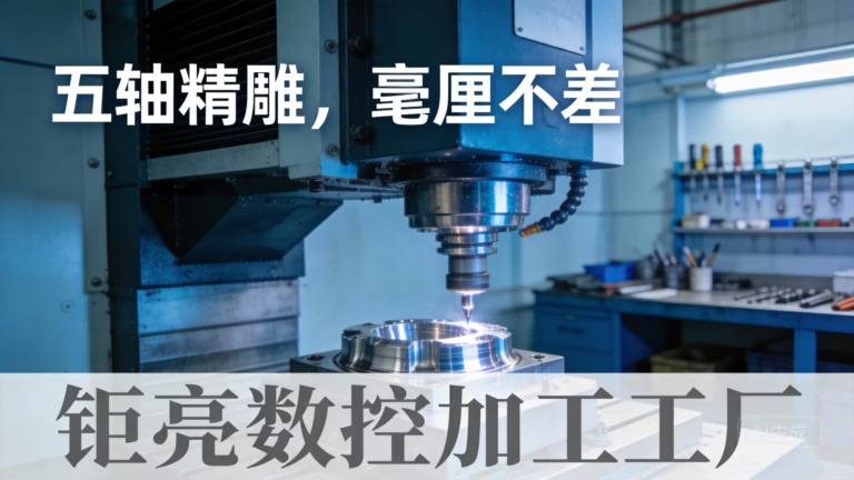
What a CNC machine actually does to metal
CNC machining is subtractive. You start with solid stock, a plate, a bar or a casting, and a rotating cutter removes material along a toolpath generated from a 3D model. Nothing is formed or added. That single fact explains most of what the process can and cannot do.
The cutter has a diameter, a flute count and a reach. Every internal corner it leaves carries the radius of that cutter, and every pocket it cuts is limited by how far the tool can reach without chattering. A 12 mm end mill will not cut a 4 mm internal corner. It leaves a 6 mm radius, and someone has to either accept that or specify a smaller tool and a slower cycle.
Tolerance comes from the machine, the fixturing and the material together, not from the drawing alone. A thin wall clamped in a vise will move when the clamp comes off. A deep bore drilled from one side will drift. The drawing says ±0.005 mm; the setup decides whether that number survives.
So the real question is never "can a CNC machine cut this shape". It is whether the shape can be held, reached and measured. Those three constraints set the practical list of parts you can make with a cnc machine.
Six part families that fit the process
Prismatic parts are the core of the work. Brackets, housings, manifolds, plates, heat sinks, adapter blocks. Anything that can be described as a block with features on several faces belongs here. Three-axis work covers most of it; the fourth and fifth axes exist to reach features on the remaining faces without re-fixturing.
Rotational parts are another large family: shafts, bushings, pins, spacers, threaded inserts, valve bodies. Turning holds diameter and concentricity well, and a mill-turn center can add cross holes, flats and slots in the same setup. If your part is mostly round with a few side features, mill-turn beats two separate operations.
Thin-wall and shell parts are where the process gets harder. A 0.8 mm wall on a 6061 housing is routine with light finishing passes and proper support. A 0.3 mm wall on the same part will deflect during cutting and again when the vise releases. Below roughly 1 mm, wall thickness starts to drive cost more than geometry does.
Optical and sealing surfaces sit at the other end. Faces that must hold Ra 0.2–0.8 μm need a separate finishing pass with a sharp tool and a rigid setup. Cutting them in the same pass as roughing usually fails.
Large frames and beams are a size question rather than a geometry question. We run up to 4,000 mm on the long travel, which covers welded frame rails, gantry beams and long manifolds. Beyond that the part has to be split, and splitting introduces a joint that has to be designed, not improvised.
Small precision parts, connectors, implants, sensor bodies, are usually a volume and handling question. At 5 mm across, the cutting is easy. Holding twenty of them for a second operation is the real work.
Material decides more than the drawing does
Aluminium is the default for prototypes and for most enclosures. 6061 and 7075 cut cleanly, hold tolerance and take anodizing well. 7075 gives higher strength but machines slower and is less forgiving on thin walls. If the part will be anodized, tell us early; some alloys and some tempers finish unevenly.
Stainless 303 and 304 are common for fittings and food-contact parts. 316L shows up in medical and marine work. Stainless work-hardens, so light passes and constant feed matter more than spindle speed. 17-4PH machines well in the annealed state and can be aged afterward for strength.
Steel grades 1018, 1045, 4140 and 4340 appear in shafts, fixtures and structural parts. Tool steel is used for molds and dies, where hardness after heat treatment matters more than machined finish.
Titanium TC4 (Ti-6Al-4V) and Inconel are slow, expensive and sometimes the only option. They conduct heat poorly, so the cutter runs hot and tool life drops. Expect longer cycles and a higher price per part.
Plastics behave differently again. POM and PEEK hold tolerance well; ABS and PP move with temperature and clamp pressure. Carbon fibre is abrasive, so it eats tooling and needs dust control.
Copper and brass cut fast and finish beautifully, but they are soft and grabby. Beryllium copper adds a health-and-safety step that has to be planned, not discovered mid-run.
Cases where CNC is the wrong answer
If the part is a thin shell with uniform wall and no machined features, injection molding or die casting will beat CNC on unit cost once volume passes a few thousand pieces. CNC wins on lead time, not on volume economics.
If the geometry is a lattice, an internal cooling channel or a hollow sphere, additive is usually the only route. We run 3D printing for exactly those cases and machine the critical faces afterward.
If the part is a flat panel with holes and bends, sheet metal fabrication is faster and cheaper. Adding a machining step to a bent panel usually just adds cost.
If the tolerance is looser than ±0.1 mm and the shape is simple, casting or extrusion plus a light finish pass may be enough. Machining the whole part from solid wastes material and cycle time.
The honest boundary is this: CNC is best when the part is solid, has features on more than one face, and needs to hold a real tolerance. Outside that, there is usually a better process.
Part type against process fit
Use this to pick a starting process before you send a drawing.
| Part type | Typical size | Best process | Watch out for |
|---|---|---|---|
| Bracket or housing | Up to 750 mm | 3-axis milling | Thin walls under 1 mm |
| Shaft or bushing | Ø5–200 mm | CNC turning | Concentricity across two setups |
| Manifold or valve body | Up to 600 mm | 4-axis / 5-axis | Deep cross holes and burrs |
| Long frame or beam | Up to 4,000 mm | Large-travel milling | Part splitting and joint design |
| Lattice or hollow shell | Any | 3D printing | Post-machining of mating faces |
| Flat panel with bends | Up to 3,000 mm | Sheet metal | Hole position after bending |
| Implant or connector | Under 50 mm | 5-axis / mill-turn | Deburring and surface finish |
| Mold or die insert | Up to 500 mm | 3-axis + EDM | Hardness after heat treatment |
The short version
If your part is solid, needs two or more machined faces, and holds ±0.05 mm or tighter, machine it. If it is a thin uniform shell in high volume, or a lattice, pick another process first and machine only what has to be precise.
Common questions
How small can a CNC-machined feature be?
It depends on the tool, not the machine. A 1 mm end mill can cut a slot around 1.2 mm wide and about 3 mm deep before deflection takes over.
Below that, micro-tooling exists but tool life drops fast and the cycle time rises sharply. If your design needs sub-millimetre slots, send the drawing and we will tell you what is realistic.
Can CNC machines cut hardened steel?
Yes, with the right tooling. Material up to roughly 45 HRC can be milled with carbide and conservative parameters.
Above that, the usual route is to machine soft, heat treat, then finish by grinding or EDM. Machining after hardening rarely holds tolerance well.
What surface finish can I expect?
As-machined surfaces land around Ra 1.6–3.2 μm. With a dedicated finishing pass we reach Ra 0.8–1.6 μm, and on sealing or optical faces Ra 0.2–0.8 μm.
Tell us which faces actually need the fine finish. Specifying it everywhere adds cycle time for no benefit.
Do I need a 5-axis machine for my part?
Usually not. Most parts are cut faster on three axes because the setup is simpler and the tool is more rigid.
Five-axis earns its place when a feature sits on an angle that would need three or four separate setups, or when a single setup is needed to protect a datu</br>m relationship.
What file formats do you need for a quote?
A STEP or IGES file plus a PDF drawing with tolerances, material and finish is enough. If you only have an STL, send it and we will work from it.
A DFM analysis comes back with the quote within 12 hours, so you can fix problems before the first cut.
Can you handle one-off parts?
Yes. There is no minimum order quantity. We run single prototypes and production runs past 10,000 pieces on the same floor.
For a single part, the cost is dominated by programming and setup, not by material or cycle time.
Send the drawing, get a real answer
Upload your 3D model and we will confirm the process, tolerance and finish, or tell you which process fits better.
12-hour quote100% inspectionNDA on request
More from the shop floor
We publish setup notes, tooling trials and inspection data from the factory floor.











