
What Does the CNC in CNC Machines Mean?
CNC stands for Computer Numerical Control: a computer reads a program of coordinates and drives the machine's axes to cut a part. This page explains the full chain from CAD file to finished surface, where the process hits its limits, and how to tell when CNC is the right route for your part.
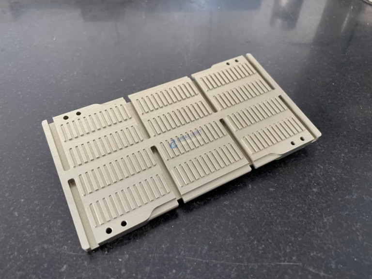
What does the CNC in CNC machines mean, word by word
Take the three letters apart. Computer means a controller, not a laptop. It is the industrial PC or motion controller mounted on the machine cabinet. Numerical means the part geometry is expressed as numbers: X, Y, Z coordinates, feed rates in mm/min, spindle speed in rpm. Control means the controller closes the loop, reading position feedback and correcting the axes thousands of times per second.
That last word matters most. A manual mill operator watches a dial and turns a handwheel. A CNC machine compares the commanded position with the actual position from a linear scale or encoder, then adjusts the servo until the error is near zero. The operator's skill moves out of the cut and into the setup, the tooling choice, and the program.
So the CNC in CNC machines means the cutting motion is directed by stored numbers rather than by hand. The same program can run 1 part or 10,000 parts. That repeatability is the whole point.
- 1ComputerMachine-mounted controller that executes the part program.
- 2NumericalGeometry and feed data written as coordinates and rates.
- 3ControlClosed-loop correction of axis position in real time.
From CAD file to cut metal
The chain starts with a 3D model. A CAM programmer sets the stock size, chooses tools, and defines toolpaths. The post-processor converts those paths into G-code for the specific machine and controller. A typical G-code line looks like G01 X25.4 Y10.0 Z-3.0 F250, which means move in a straight line to that point at 250 mm/min.
The controller reads the program block by block. It plans acceleration and deceleration, checks tool offsets from the offset table, and applies cutter compensation so the finished wall lands on the nominal dimension. On a lathe the same logic applies, but the part spins and the tool travels.
Setup is where most variation enters. Workholding, tool runout, and thermal drift all show up in the first few parts. A probe or touch-off routine sets the work origin. Once the offsets are locked, the machine repeats within its positioning accuracy.
- 1CADNominal geometry, tolerances, and datum scheme.
- 2CAMTool selection, stepover, depth of cut, lead-in moves.
- 3PostMachine-specific G-code and M-code output.
- 4Prove-outFirst-article check before the run continues.
What 3, 4, and 5 axes actually change
A 3-axis mill moves the table and spindle in X, Y, and Z only. The tool always approaches from one direction, so undercuts and deep side features need multiple setups. This is the workhorse for plates, brackets, and housings with features on one or two faces.
A 4-axis machine adds rotation about one axis, usually A. The part can be indexed to new faces without re-fixturing, or turned slowly while cutting a cylindrical feature. A 5-axis machine adds a second rotary axis, so the tool can tilt and reach compound angles in one setup. That matters for impellers, turbine blades, and parts with holes on many faces.
More axes is not automatically better. Five-axis toolpaths are slower to program, and the rotary axes add their own positioning error. Use them when the geometry demands it or when fewer setups cut total cost.
- 13-axisSimple prismatic parts, one or two setups.
- 24-axisIndexed faces and cylindrical work.
- 35-axisCompound angles and contoured surfaces in one setup.
Where the accuracy actually comes from
Accuracy is a stack of small errors, not one number. Machine positioning, spindle thermal growth, tool runout, workpiece deflection, and fixture stiffness all contribute. A machine rated at ±0.005 mm can only hold that on a rigid setup with light finishing passes and a sharp tool.
Surface finish is a separate target. As-machined surfaces typically land at Ra 1.6–3.2 μm. A controlled finishing pass can reach Ra 0.8–1.6 μm. Fine finishes down to Ra 0.2–0.8 μm need small stepovers, higher spindle speed, and often a dedicated finishing tool.
Thin walls are the classic failure case. A 0.5 mm wall in aluminium will chatter or spring away from the cutter. The fix is support, not more spindle speed. Sometimes the right answer is a different process entirely.
- 1Rigid setupThe single largest lever on achieved tolerance.
- 2Thermal driftWarm-up and in-process checks reduce variation.
- 3Tool conditionWorn edges push dimensions and raise Ra.
When CNC is the wrong choice
CNC removes material, so it wastes stock. For a part that is mostly a hollow shell, deep pockets or a casting will be cheaper at volume. A die-cast or vacuum-cast blank with a light finish pass can beat a part cut from solid.
Hardened tool steel above roughly 45 HRC cuts poorly on standard carbide. That work belongs on EDM or grinding. Very soft elastomers also cut badly, because they deflect instead of shearing cleanly.
For a single plastic enclosure with simple geometry, 3D printing may be faster and cheaper. CNC earns its place when you need metal, tight tolerance, or a surface that must look and feel machined.
- 1Volume shellsCasting plus finishing often costs less.
- 2Hardened steelAbove 45 HRC, plan for EDM or grinding.
- 3Simple plasticPrinting can win on speed for one-off parts.
Which route fits which part
Judge by geometry, material, and quantity, not by habit.
| Part profile | Better route | Reason |
|---|---|---|
| Prismatic metal bracket, 1–500 pcs | 3-axis CNC | One setup, standard tooling, fast prove-out |
| Shaft with cross-holes, 50–5,000 pcs | Mill-turn or 4-axis | Fewer setups, better concentricity |
| Impeller with compound angles | 5-axis CNC | Undercuts and blended surfaces in one setup |
| Hollow housing, 10,000+ pcs | Die casting + finish pass | Less stock removal, lower cycle time |
| Mold steel above 45 HRC | EDM or grinding | Carbide edges wear too fast |
| Single plastic cover, simple shape | 3D printing | No fixturing, no toolpath programming |
The short answer
If your part is metal, needs tight tolerance, and the geometry has to be cut rather than formed, choose CNC. If it is a hollow shell at high volume or a hardened mold insert, choose casting, EDM, or grinding instead.
Common questions
Is CNC the same as automation?
No. CNC is a control method for a machine tool. Automation is a broader idea that includes robots, conveyors, and inspection cells.
A CNC machine can run unattended for a while, but it still needs an operator to load stock, change tools, and check the first part.
Does a higher axis count always give a better part?
No. Each rotary axis adds its own positioning error and programming time. Use 5-axis when the geometry needs it or when fewer setups reduce total cost.
Many parts are cheaper and just as accurate on a well-fixtured 3-axis machine.
How tight can CNC tolerances realistically get?
A well-controlled process can hold ±0.005 mm on critical features in aluminium and mild steel. That requires a rigid setup, a sharp tool, and a finishing pass.
Larger parts and harder materials open that window. Thin walls are the most common reason a tolerance cannot be held.
What file format do you need for a quote?
A STEP or IGES solid model plus a 2D drawing with tolerances, datums, and finish callouts. The drawing carries information the 3D model does not.
If you only have a 2D drawing, we can still quote, but expect questions about critical features.
Can CNC cut any metal?
Most aluminium, stainless, steel, copper, brass, and titanium grades cut well with the right tools and speeds. Titanium and Inconel need slower parameters and more coolant.
Very hard or abrasive materials are usually sent to EDM or grinding instead.
How do you keep my design confidential?
Uploads are handled as confidential. An NDA is available on request before you send files.
Access to customer data is restricted to the engineers working on the quote and the run.
Send a drawing, get a real answer
Quotation and free DFM analysis within 12 hours. No minimum order quantity, from one prototype to 10,000+ part runs.
12-hour quote100% inspectionNo MOQ
More from the shop floor
We publish setup notes, tooling trials and inspection data from the factory floor.











