
What Does Tooling Mean in CNC Machining?
Tooling in CNC machining is everything between the spindle and the part: the cutter, the holder, the fixture, and the offsets that tie them to the program. This page explains those four layers for engineers and buyers who have to judge a quote. Read it and you can tell which parts are cheap to tool up, which ones are not, and where a tight tolerance actually comes from.
In this article
- 1
- 2
- 3
- 4
- 5
- 6
- 7
- 8
Key takeaways
What tooling in CNC machining actually covers
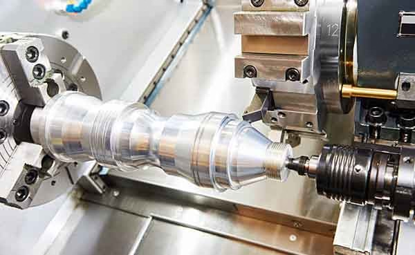
Ask five people on a shop floor and you get five answers. Tooling in CNC machining means the physical set that turns a CAM file into chips: the cutting tool, the tool holder, the workholding, and the offset data that tells the control where the cutting edge really is. It is a chain. The weakest link sets the result.
That chain has a cost side too. On a typical aluminum bracket, the cutter is a few dollars and the fixture may be a few hundred. On a thin-wall titanium housing, the fixture and the tool path strategy can outweigh the material cost. When a quote looks high, tooling is often the reason.
The word also gets used for mold tooling and die casting inserts, which is a different subject. Here we stay on the subtractive side: milling, turning, and mill-turn work where the cutter touches the part directly.
One useful test. If you changed only the tool geometry and the part failed, you had a tooling problem. If you changed the program and the part passed, you had a programming problem. Separating the two saves days of arguing.
- 1Cutting toolEnd mills, drills, taps, reamers, boring bars, inserts.
- 2Tool holderCollet chuck, hydraulic, shrink fit, shell mill arbor.
- 3WorkholdingVise, soft jaws, fixture plate, vacuum, chuck.
- 4Offsets and setupTool length, diameter comp, work offset, probing.
Cutting tools: geometry decides the cut
The cutter removes material, and its geometry sets the load it can carry. A 3-flute end mill in 6061 aluminum at 12 mm diameter can run deep axial cuts because the chip has room to clear. The same diameter in 17-4PH stainless needs more flutes and a smaller radial engagement, or the edge chips within minutes.
Coating matters less than people expect. For aluminum, uncoated or ZrN is usually enough. For stainless and titanium, AlTiN or AlCrN holds up better at the 45–60 m/min surface speeds those alloys allow. Coatings raise tool life. They do not rescue bad speeds and feeds.
Corner radius is a common miss in DFM. A sharp internal corner has to be cut by a tool with a matching radius, so a 0.5 mm corner needs a 1 mm cutter that cannot reach deep without deflection. Adding R1 or R2 to internal corners often removes a whole finishing operation.
Tool reach is the other limit. A cutter that sticks out 4× its diameter will deflect. If a feature sits at the bottom of a deep pocket, either accept a looser tolerance on that wall or add a second setup with a shorter tool.
Holders and runout: where tolerance is won or lost
The holder transfers spindle torque and, more importantly, spindle position. Runout is the error. A standard collet chuck may show 0.02–0.03 mm at 3× diameter. A hydraulic or shrink-fit holder can hold under 0.005 mm. That difference lands directly on your wall position.
This is why a shop can promise ±0.005 mm on one part and refuse it on another with the same geometry. The deciding factor is whether a low-runout holder is available in that size and whether the tool can be reached without an extension.
Balance matters at speed. Above roughly 15,000 rpm, an unbalanced holder with a long gauge length will vibrate, and vibration shows up as chatter marks on the floor of a pocket. Short gauge length beats high-precision runout when you have to choose.
Holders wear. A collet that has been clamped a few hundred times loses grip and the runout drifts. Shops that track holder life get more consistent parts than shops that replace cutters only.
Workholding and fixtures: the setup that holds the part still
A fixture locates the part and resists cutting force. If it moves, the part moves, and every tolerance downstream is meaningless. For a 400 × 400 mm plate, a vise alone will not do. A fixture plate with clamps at the corners and support under the cut zone will.
Thin walls are the hard case. Cutting force pushes a 1 mm wall away from the cutter, then the wall springs back and the finished thickness is wrong. The fix is usually support: soft jaws shaped to the profile, a wax or low-melt fill, or a change in the tool path so the finishing pass takes load from both sides.
Five-axis work changes the rules because the part tilts. A fixture has to hold through the rotation without colliding with the spindle. This is where a well-made tombstone or modular plate pays for itself across a production run.
For prototypes, soft jaws machined in place are usually the fastest route. For a 10,000-part run, a dedicated fixture with quick-clamp geometry cuts load and unload time, which is often the real cost driver.
Offsets, probing and the setup loop
A perfect cutter in a perfect holder still cuts in the wrong place if the offset is wrong. Tool length and diameter offsets tell the control where the edge is. Work offsets tell it where the part is. Both drift with temperature and with tool changes.
Probing closes the loop. A spindle probe can measure a bore, update the work offset, and re-cut a feature without a manual reset. On parts with ±0.005 mm callouts, this is often the difference between a first-article pass and a second setup.
In-process measurement is not free. A probing cycle adds time to every part. Use it where the tolerance genuinely needs it. On a bracket with a ±0.1 mm hole, a caliper check at the end is enough.
Keep the setup record. Tool numbers, holder part numbers, gauge lengths and offset values should travel with the job. When a part is re-ordered six months later, that record is what makes the second run match the first.
Five checks before you approve a tooling plan
Run these in order. Each one can kill the plan.
- 1Check cutter reach against feature depthCompare the deepest pocket to the tool diameter. If reach exceeds 4× diameter, plan a shorter tool and a second setup.
- 2Check runout need against toleranceBelow ±0.02 mm, ask for a hydraulic or shrink-fit holder. Above that, a good collet chuck is fine.
- 3Check internal corner radiiAny corner smaller than R1 forces a small cutter. Ask whether R1 or R2 is acceptable before quoting.
- 4Check fixture access for all five sidesOn 5-axis parts, confirm the clamps clear the spindle at every rotation angle.
- 5Check material machinability6061 and 303 stainless cut fast. Inconel and Ti-6Al-4V need lower surface speed, more passes and more tool changes.
Tooling choice by part and tolerance
Match the case to the tooling route. Cells are guides, not rules.
| Case | Typical tooling | Reasonable tolerance | Watch out for |
|---|---|---|---|
| Flat plate, loose tolerance | Standard end mill, vise | ±0.05 mm | Vibration on thin sections |
| Housing with deep pockets | Long-reach cutter, soft jaws | ±0.02 mm | Deflection at 4× reach |
| Thin-wall part | Profile soft jaws, wax fill | ±0.02 mm | Spring-back after cutting |
| 5-axis contoured part | Tombstone or modular plate | ±0.005–0.01 mm | Clamp collisions |
| Turned shaft, tight bore | Boring bar, reamer, collet chuck | ±0.005 mm | Chatter in long bores |
| Titanium or Inconel part | AlTiN cutter, rigid holder | ±0.01 mm | Rapid tool wear |
The trade-off in one line
If the feature is reachable with a standard cutter in a low-runout holder, tooling is cheap and fast. If it needs a long-reach tool, a custom fixture, or a non-standard corner radius, expect more cost and more lead time, and decide early whether the design can be relaxed.
Tooling questions engineers ask
Is tooling the same as a mold?
No. In die casting and injection molding, tooling means the mold or die, which is a capital item that can cost more than the parts. In CNC machining, tooling means cutters, holders, fixtures and offsets, and it is mostly consumed or reused across jobs.
The two get mixed up because both appear as a line item on a quote. Ask which one is meant before you compare prices.
Does tooling change the unit price?
Yes, but indirectly. Cutting tools wear and get replaced, so harder materials raise the per-part cost through tool life. Fixtures are a one-time cost that spreads across the run.
A part that needs a custom fixture is expensive at quantity 1 and cheap at quantity 1,000. A part that cuts with a standard end mill in a vise is cheap at both ends.
How do I know if my design needs custom tooling?
Look at three features: internal corner radii, pocket depth relative to width, and wall thickness. If corners are R1 or larger, pockets are shallower than 4× the cutter diameter, and walls are over 1.5 mm, standard tooling usually works.
If any of those is outside the range, ask for a DFM review before you commit to the design.
Can you machine a part without a fixture?
Sometimes. A single prototype in a vise or on a vacuum plate is often enough. The moment the part needs a second operation, or the tolerance tightens, a fixture becomes the cheaper option because it removes re-alignment error.
We decide this per part, not per customer.
What tolerance can standard tooling hold?
With a standard collet chuck and a sharp cutter, ±0.02 mm is a comfortable target on most aluminum and stainless parts. Below that, low-runout holders, probing and temperature control come into play.
Our general capability is ±0.005 mm with the right holder and setup, and we will say so when a feature cannot reach it.
Does tooling affect surface finish?
Yes. A worn cutter or a vibrating holder leaves marks that no finishing pass removes. As-machined finish typically lands around Ra 1.6–3.2 μm; a controlled finishing pass with a sharp tool reaches Ra 0.8–1.6 μm, and fine work can reach Ra 0.2–0.8 μm.
If the print calls for a fine finish, say so before the tooling plan is set.
Send the drawing, get a tooling-aware quote
Upload the CAD file and we will review corner radii, pocket depth and wall thickness against the tooling we have, then quote with the setup included.
12-hour quote100% inspectionNo minimum order quantity
More from the shop floor
We publish setup notes, tooling trials and inspection data from the factory floor.











