
What Is a CNC Machine Tool?
What is a cnc machine tool, in practical terms? It is a machine that moves a cutting tool along programmed coordinates instead of handwheels. This page covers how frame, control, and tooling work together, which part shapes suit each configuration, and where the process stops paying off.
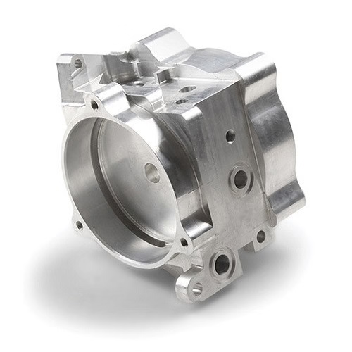
What is a cnc machine tool made of?
What is a cnc machine tool, in the plainest sense? It is a machine that removes material by following a stored program instead of a handwheel. The program is a list of coordinates, feed rates, spindle speeds, and tool changes. The machine runs it without an operator turning a dial for every pass.
Three subsystems have to agree. The mechanical frame carries the slides, spindle, and workholding. The control reads G-code and closes the position loop on each axis. The cutting tool actually shears the material. A weak link in any one of them shows up on the finished part.
Most shops describe a machine by its linear axes. A 3-axis mill moves X, Y, and Z. A rotary table adds a fourth axis, and a tilting head or trunnion adds the fifth. The axis count matters because it decides how many faces you can cut in one setup.
The frame is the part buyers rarely ask about and engineers should. Cast iron or polymer concrete damps vibration. Linear guides hold position repeatably. A 7,600 m² shop running 127 machines learns quickly which frames hold tolerance after year three and which ones drift.
How the control turns a drawing into cuts
The chain starts with a CAD model. CAM software converts that model into toolpaths, then into G-code. The control reads the code block by block, interpolating straight moves and arcs while the servo loop corrects position thousands of times per second.
Accuracy comes from two numbers that are often confused. Repeatability is how close the machine returns to the same point. Accuracy is how close that point matches the drawing. A machine can repeat within ±0.002 mm and still sit 0.02 mm off nominal if it was never calibrated.
Thermal growth is the quiet enemy. A spindle running at 12,000 rpm warms and lengthens. On a long aluminum cut, that shift can move the tool tip a few microns. Shops that hold ±0.005 mm run warm-up cycles and let the machine idle before the first finishing pass.
Cutting force pushes back. The tool deflects, the part deflects, and the fixture gives a little. Roughing passes remove most of the volume with heavy loads. Finishing passes take light cuts, sometimes 0.1 mm radial, to keep that deflection small enough to stay in tolerance.
Three, four, and five axis: what each one buys you
A 3-axis machine cuts from one direction. The part sits on the table, and every feature has to be reachable from above or from a flipped setup. It is the cheapest way to make a flat plate with holes, pockets, and a chamfer.
A 4-axis machine adds a rotary table, usually turning about X or Y. Now you can cut flats around a shaft without unclamping. Engine parts, connectors, and long brackets benefit most. The rotary table at GreatLight is Ø400 mm, which sets a practical limit on part diameter.
A 5-axis machine tilts the tool or the part so the cutter approaches at an angle. Undercuts, deep pockets with curved walls, and impeller blades become single-setup jobs. Sixteen simultaneous 5-axis centers handle the work that no amount of fixturing can fix on three axes.
More axes are not automatically better. A 5-axis cycle costs more per hour and takes longer to program. If your part has three flat faces and a bolt pattern, a 3-axis machine with a soft jaw will beat it on price and lead time every week.
The cutter decides the surface you get
The spindle only moves the tool. The tool does the cutting. Carbide end mills cover most work. Coatings such as TiAlN extend life on steel, while uncoated polished flutes run cooler in aluminum. A 3-flute cutter clears chips better in aluminum than a 4-flute one.
Chip evacuation is a real constraint, not a footnote. Deep pockets trap chips, and a recut chip breaks edges fast. Through-spindle coolant or air blast solves most of it. If the pocket is deeper than three times the cutter diameter, plan the toolpath to lift and clear.
Surface finish depends on feed per tooth, spindle speed, and tool runout. A dialed-in machine reaches Ra 0.8–1.6 μm as a normal cut. Pushing to Ra 0.2–0.8 μm usually means a separate finishing pass with a smaller stepover, or a subsequent lapping or polishing step.
Tool runout is the one number machinists chase. A cutter held 0.01 mm off center cuts one flute harder than the others. That single flute wears first, the finish goes streaky, and the dimension drifts. Good holders cost money because they remove that variable.
Matching part geometry to machine setup
Read the row that looks like your part, then the tradeoff column.
| Part feature | Setup to choose | Typical limit | Tradeoff |
|---|---|---|---|
| Flat plate, holes, pockets | 3-axis, one setup | Tolerance ±0.005 mm | Lowest cost per part |
| Shaft with flats and slots | 4-axis with rotary table | Rotary table Ø400 mm | Fewer setups, longer cycle |
| Curved walls, undercuts | 5-axis simultaneous | Reach limited by tool length | Higher hourly rate |
| Two-sided flat housing | 3-axis, two setups | Datum shift adds error | Cheap, needs good fixtures |
| Large weldment, 3 m long | 3-axis with 4,000 mm travel | 4,000 × 400 × 150 mm | Rigidity drops at extension |
| Impeller or bladed disk | 5-axis simultaneous | Tool access is the limit | Programming time dominates |
Pick the setup the geometry demands
If the part is prismatic with reachable faces, run 3-axis and put the money into fixturing. If two or more faces must be cut in one datum, add the fourth axis. Go 5-axis only when the geometry cannot be reached any other way.
Questions engineers ask next
What materials can a cnc machine tool cut?
Aluminum grades 6061, 7075, and 2024 are the everyday choice, along with 303, 304, and 17-4PH stainless, 1018 and 4140 steel, and copper alloys such as C36000.
Titanium TC4 (Ti-6Al-4V), Inconel, and magnesium AZ31B are also routine here. Plastics including POM, PEEK, and ABS machine cleanly with sharp tooling and light cuts.
How tight a tolerance is realistic?
On a calibrated machine with stable temperature, ±0.005 mm holds on a feature that has good access and a rigid setup. That is ±0.0002 in.
Tolerance is per feature, not per part. A deep bore far from the fixture can be looser than a shallow pocket near a clamp. Tell us which dimensions actually matter.
Is CNC machining a fit for prototypes?
Yes. There is no minimum order quantity, so a single prototype and a 10,000-part run use the same process. Quotation and DFM feedback come back within 12 hours.
For prototypes, machining usually beats tooling-based processes because there is no mold to cut. That changes when the part count climbs past a few thousand and the geometry stays fixed.
What surface finishes are available?
As-machined surfaces land around Ra 1.6–3.2 μm. A controlled finishing pass reaches Ra 0.8–1.6 μm, and fine work goes to Ra 0.2–0.8 μm.
After machining, parts can be anodized, plated, powder coated, bead blasted, or laser marked. Laser marking holds a minimum character height of 1.5 mm.
How do you check parts before shipment?
Every part is inspected before it ships. That includes a raw material check, in-process monitoring, and a final inspection, with reports available on request.
The historical qualification rate is 99.99%. For regulated work, the shop holds ISO 9001:2015, IATF 16949:2016, ISO 13485:2016, and ISO 27001:2022.
Can you work under an NDA?
Yes. Uploads are kept secure and confidential, and a non-disclosure agreement is available on request before any files move.
If your drawings carry export or IP restrictions, say so at the quote stage so the right controls are applied from the first cut.
Send the drawing, get a real answer
Upload your CAD file and get a quotation with DFM feedback within 12 hours. No minimum order quantity, from one prototype to a 10,000-part run.
12-hour quote100% inspectionNo MOQNDA on request
Follow GreatLight
We publish setup notes, tooling trials and inspection data from the factory floor.











