
What Is a Machine Tool in CNC?
A machine tool in CNC is the physical machine that holds the workpiece and the cutting tool, while a controller drives every axis, spindle speed, and tool change from a program. This page breaks down the subsystems, the accuracy limits they set, and which machine type fits which part. It is written for design engineers and buyers who need to judge a process, not memorize a definition.
Key takeaways
What a machine tool in CNC actually is
A machine tool is the metal-cutting machine itself: the frame, the spindle, the axis slides, the workholding, and the tool changer. In a CNC machine tool, an onboard controller reads a program of G-code and M-code and turns it into motion. The operator loads the part and the program; the machine executes the cuts.
The distinction matters when you read a quote or a drawing note. "CNC" describes how the machine is driven, not what it can do. Two machines can both be called CNC and still differ by a factor of ten in stiffness, spindle power, and achievable tolerance. The machine tool is the constraint; the controller only follows orders.
In practice, a machine tool in CNC is judged by four numbers: axis travel, spindle speed and power, positioning accuracy, and repeatability. Travel tells you the largest part envelope. Positioning accuracy tells you how close the machine can get to a commanded point. Repeatability tells you how well it returns to the same point after many cycles, which is what actually holds a tolerance across a production run.
- 1Machine toolPhysical cutting platform: frame, spindle, axes, tool changer.
- 2CNC controllerComputer that executes the part program and compensates errors.
- 3Part programG-code and M-code generated from the CAM model.
The subsystems that decide accuracy
The bed and column are usually cast iron or polymer concrete. Their job is to absorb cutting force without flexing and to damp vibration. A light frame will chatter on a deep pocket in 4140 steel, and chatter shows up as poor surface finish and oversize dimensions. Mass is not a marketing number here; it is the reason a heavy mill can take a 6 mm depth of cut where a light one takes 1 mm.
Linear guides and ballscrews convert motor rotation into axis motion. Roller-type guides carry heavier loads; ball-type guides run faster with less friction. Ballscrew pitch error and thermal growth are mapped and compensated by the controller. On a long run, a screw that warms by a few degrees can drift tens of microns, which is why warm-up cycles and temperature compensation matter on tight work.
The spindle sets the cutting envelope. Speed, in rpm, pairs with tool diameter to give surface speed; power and torque decide how hard you can push. A high-speed spindle at 20,000 rpm suits a Ø3 mm end mill in aluminium. A geared spindle at 6,000 rpm with high torque suits a Ø50 mm face mill in steel. Choosing the wrong spindle means either burning tools or stalling the cut.
The controller closes the loop. It reads feedback from encoders or glass scales, compares it to the commanded path, and corrects the drives many times per second. It also handles tool length offsets, cutter compensation, and adaptive feed control. This is where a machine earns its repeatability, because the mechanical parts only need to be predictable, not perfect.
- 1FrameCast iron or polymer concrete; damps vibration and resists deflection.
- 2Guides and screwsSet load capacity, rapid speed, and positioning accuracy.
- 3SpindleSets rpm, torque, and the largest practical tool diameter.
- 4ControllerExecutes the program and applies error compensation.
How axis count changes the parts you can make
A 3-axis machine moves the tool in X, Y, and Z while the part stays fixed. It is simple, rigid, and fast. It handles plates, brackets, housings, and any feature you can reach from one direction. If a part has holes on five faces, a 3-axis machine needs multiple setups, and each setup adds a re-clamping error and a queue slot.
A 4-axis machine adds a rotary axis, usually around X or Y. The part turns while the tool cuts, so you can machine a shaft, a cylinder with cross holes, or a cam profile without re-fixturing. This is the workhorse for round and prismatic parts that need features on more than one face.
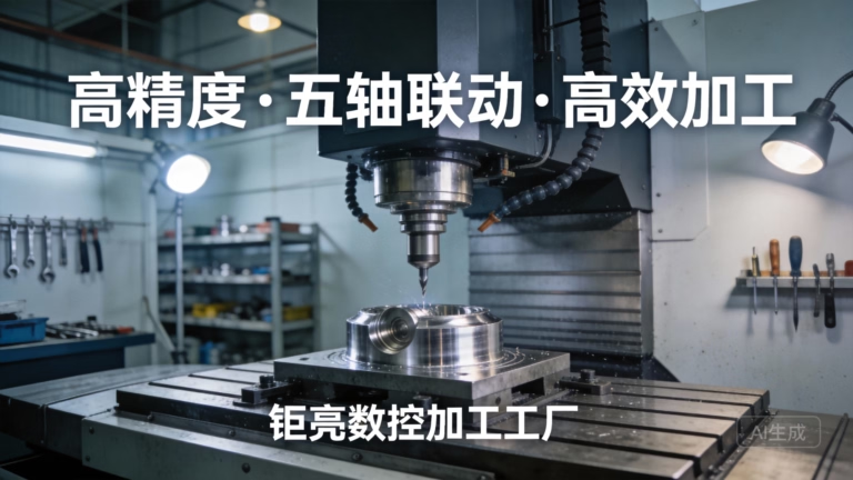
A 5-axis machine adds two rotary axes, either as a trunnion table or a swivel head. The tool can approach the part from nearly any direction, so undercuts, deep cavities, and contoured surfaces are cut in one setup. It also lets you keep a short, stiff tool by tilting it, which improves surface finish on tall walls. The trade-off is programming time and a smaller work envelope for the same footprint.
A mill-turn center combines turning and milling on one platform. The part spins like a lathe, then a milling spindle cuts off-axis features. For a part like a hydraulic manifold with turned diameters and cross-drilled ports, this removes a second machine from the route and cuts the handling error between operations.
- 13-axisFlat plates and open pockets cut from one direction.
- 24-axisShafts and cylinders with cross features, one setup.
- 35-axisUndercuts and contoured surfaces, short rigid tools.
- 4Mill-turnTurned and milled features on one platform.
Where machine tools reach their limits
Tolerance is a system result, not a single spec. A machine rated at ±0.005 mm can hold that on a well-supported feature in a stable material. The same machine will struggle on a thin wall that deflects under cutting force, or on a deep bore where a long tool bends. When a drawing calls for a tight tolerance on a flexible feature, the fix is often a design change, not a better machine.
Thermal behavior sets the practical floor. Spindles, motors, and ballscrews generate heat. A cold machine at 7:00 am and a warm machine at 3:00 pm are not the same machine. Shops that run tight work use warm-up routines, coolant temperature control, and in-process probing. Without these, a ±0.005 mm callout is a hope rather than a plan.
Material pushes back. Aluminium 6061 cuts freely at high speed and holds a fine finish. Stainless 316 work-hardens and needs a rigid setup with a constant feed to avoid rubbing. Inconel and titanium generate heat at the cutting edge and wear tools quickly, so spindle torque and coolant delivery matter more than peak rpm. Choosing the machine for the material is as important as choosing it for the geometry.
Part size closes the loop. A 4,000 mm travel machine exists for long frames and rails. Putting a small fitting on it wastes the envelope and can reduce accuracy because the axes travel far from the stiff center of the bed. The right machine is the smallest one that fits the part with a margin for fixturing.
- 1Thin wallsDeflect under cutting force; tolerance suffers before the machine does.
- 2Deep boresLong tools bend; use a shorter tool or a different process.
- 3HeatWarm-up and temperature control protect tight tolerances.
- 4Hard alloysNeed torque, rigidity, and coolant more than high rpm.
What this means when you place an order
When you send a drawing, the shop maps features to machines. A part with tight bores on two perpendicular faces is a candidate for 5-axis or mill-turn, because one setup removes the stack-up error. A simple plate with a flatness callout is a 3-axis job, and quoting it on a 5-axis machine only adds cost.
Ask which machine will run the part and what the setup count is. Setup count drives both lead time and accuracy. Every extra clamping operation adds a fixture, a re-zero, and a chance for a chip to sit under the part. A shop that can cut a complex part in one setup is usually the better choice for tight work.
Inspection closes the argument. A machine tool in CNC only proves its accuracy through measurement. We inspect 100% of parts before shipment, with raw material checks, in-process monitoring, and final inspection, and we provide reports on request. If a feature is outside tolerance, the report shows it before the parts leave the floor.
For prototypes, machine choice also affects speed. A 3-axis machine can start cutting within hours of a drawing review. A 5-axis program takes longer to verify but removes later operations. If the part will go to production, the prototype should be made on the same class of machine, so the process transfers without a redesign.
- 1One setupFewer clamps, less stack-up error, tighter results.
- 2Right sizeUse the smallest machine that fits the part plus fixturing.
- 3Inspection100% inspection before shipment; reports on request.
Machine type vs. part geometry
Use this table to pick the starting machine type before quoting.
| Machine type | Typical part | Setup count | Watch out for |
|---|---|---|---|
| 3-axis mill | Plates, brackets, flat housings | One to three | Re-clamping error between faces |
| 4-axis mill | Shafts, cams, cylinders with ports | One | Rotary axis balance at high rpm |
| 5-axis mill | Impellers, undercuts, contoured molds | One | Programming time and envelope loss |
| Mill-turn center | Manifolds, fittings, turned-milled parts | One | Tool clearance near the chuck |
| Long-travel mill | Rails, frames up to 4,000 mm | One to two | Axis drift far from bed center |
| Lathe with live tooling | Round parts with cross holes | One | Limited milling torque on small tools |
The short verdict
If the part is flat and open, use a 3-axis machine and save the cost. If it has features on multiple faces or undercuts, use 5-axis or mill-turn and pay for one setup instead of five. Match the machine to the geometry first; then talk about tolerance.
Frequently asked questions
Is a CNC machine tool the same as a machining center?
A machining center is one type of machine tool: it has an automatic tool changer and usually a vertical or horizontal spindle. A lathe, a grinder, and an EDM are also machine tools, but they cut with different mechanics.
When a drawing says "CNC machined," it usually means milling or turning on a machining center or a lathe, not grinding or EDM.
How do I know which machine will hold my tolerance?
Start from the feature, not the machine. A supported feature in aluminium is easy; a thin wall or a deep bore is hard. Then check the setup count: more setups mean more error.
A shop holding ±0.005 mm will use temperature control, sharp tooling, and in-process checks. Ask what they do on your specific feature.
Does a 5-axis machine always give a better finish?
No. It gives you one setup and the ability to tilt a short tool into a corner. On a simple flat part, a 3-axis machine with a rigid setup can finish just as well and cost less.
Use 5-axis when the geometry demands it, not as a default.
What materials can a CNC machine tool cut?
Aluminium, stainless steel, carbon steel, tool steel, copper and brass, titanium, Inconel, magnesium, and engineering plastics. Each material changes the cutting parameters and sometimes the machine choice.
Inconel and titanium need more torque and coolant; plastics need sharp tools and controlled feed to avoid melting.
How do you inspect parts after machining?
We check raw material on arrival, monitor dimensions in process, and inspect 100% of parts before shipment. Reports are available on request.
For tight features, the report lists the measured values against the drawing so you can see margin, not just pass or fail.
Can you machine a single prototype?
Yes. There is no minimum order quantity, from one prototype to 10,000+ part runs. A quotation and free DFM analysis come back within 12 hours, and production can start within 24 hours.
Parts ship in 3–5 days for standard work.
Send the drawing, get a machine-matched quote
Tell us the material, tolerance, and quantity. We will match the part to the right machine and return a quotation with free DFM analysis within 12 hours.
12-hour quoteNo minimum order quantity100% inspectionNDA on request
More from GreatLight
We publish setup notes, tooling trials and inspection data from the factory floor.











