
What Is a CNC Mill Machine?
A CNC mill machine cuts metal, plastic and composite by moving a spinning tool along programmed axes. This page explains the spindle, the axis stack, the tool changer and the limits of the process. It is written for engineers and buyers who need to judge whether a part belongs on a mill, a lathe, or something else.
In this article
- 1
- 2
- 3
- 4
- 5
- 6
- 7
Key takeaways
What Is a CNC Mill Machine and How Does It Cut?
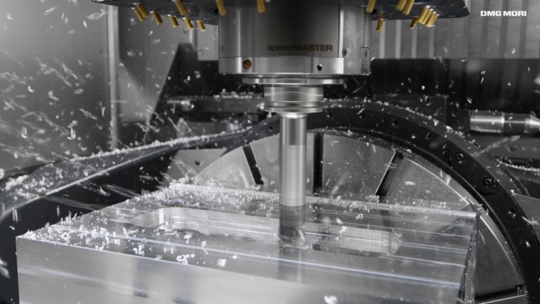
A CNC mill machine is a subtractive tool that holds a cutting tool in a spinning spindle and moves that tool relative to a clamped workpiece. The controller reads a program written in G-code and drives servo motors on each axis. Nothing about the cut depends on an operator turning a handwheel. The shape comes from the numbers.
Manual mills and CNC mills remove material the same way. The difference is who controls the feed. On a manual mill, a machinist watches the chip and feels the cut. On a CNC mill, the feed rate, spindle speed and depth of cut are set in the program and repeated for every part in the run. That repeatability is why a first article and the ten-thousandth part match.
The starting point is a 3D CAD model. CAM software reads that model, lets a programmer pick tools and toolpaths, and posts G-code. The code carries coordinates, spindle rpm, feed in mm/min, coolant commands and tool changes. A post-processor adapts the code to the specific controller on the floor.
Most milling is done with a rotating multi-flute cutter, so the surface is generated by the side or the end of the tool. That is why milling produces flats, slots, pockets, shoulders and drilled or tapped holes well. It is also why a mill is not the first choice for a part that is mostly a turned diameter.
- 1Chip loadFeed per tooth times number of teeth times rpm gives the table feed.
- 2Roughing vs finishingHeavy depth of cut removes stock; light passes hold the tolerance.
- 3Climb millingCutter rotation meets the feed, which reduces rubbing on most modern machines.
Spindle, Axes and Tool Changer: the Parts That Set the Limit
The spindle holds the tool and turns it. Speed range matters more than a single peak number. A spindle that reaches 20,000 rpm helps with small cutters in aluminium; a slower, stiffer spindle handles large-diameter tools in steel. Tool holders (BT, HSK, CAT) determine how rigidly the cutter is held and how repeatable the tool change is.
Axes define reach and geometry. A three-axis mill moves X, Y and Z, so it can cut one face per setup. A fourth axis adds rotation, usually around X or Y, letting the part be indexed without re-clamping. A five-axis machine tilts the tool or the table so the cutter stays normal to a curved surface and undercuts become reachable.
The worktable and fixturing hold the part still. Vises, soft jaws, vacuum plates, magnetic chucks and custom fixtures all trade setup time against rigidity. On thin-wall parts, the fixture often decides whether the part holds tolerance. A part that vibrates will chatter no matter how good the program is.
An automatic tool changer (ATC) swaps cutters from a carousel or chain. This is what lets one program drill, rough, semi-finish and finish without an operator touching the machine. Tool change time is short, but the real gain is that the same offsets are reused, so the geometry stays consistent across a run.
- 13-axisOne face per setup; simple and rigid.
- 24-axisIndexed rotation for multiple sides in one setup.
- 35-axisSimultaneous tilt for contoured and undercut surfaces.
Why a CNC Mill Machine Holds Tolerance
Accuracy comes from three places: the machine, the tool and the thermal state of the setup. Ballscrews, linear guides and encoder feedback keep commanded position close to actual position. A machine in good condition can hold ±0.005 mm on a stable part, but that number is not a promise for every feature on every material.
Tool deflection is the usual reason a feature drifts. A long, small-diameter end mill bends under cutting force, so a deep pocket can come out tapered. Shortening the tool, reducing the radial depth of cut, or roughing with a larger cutter and finishing with a smaller one all reduce this error.
Heat moves metal. Aluminium grows roughly 23 μm per metre per degree Celsius, steel about 11. A part that is measured hot can read differently once it cools. For tight work, let the part stabilise before final inspection, and keep the shop temperature steady.
Repeatability matters more than a single best number. If the first part and the last part of a run fall in the same band, the process is under control. GreatLight inspects 100% of parts before shipment, with raw material checks, in-process monitoring and final inspection reports available on request.
- 1Tolerance±0.005 mm (±0.0002 in) on qualified features.
- 2Fine finishRa 0.2–0.8 μm after finishing passes.
- 3Standard finishRa 0.8–1.6 μm as a typical machined surface.
When to Choose Milling, Turning or Another Process
Milling fits prismatic geometry: brackets, housings, plates, manifolds, heat sinks, fixture plates and enclosures. If the part has flat faces, pockets, slots, ribs or a mix of holes on different sides, a mill is usually the right start. Complex 3D surfaces on moulds and impellers also belong on a five-axis mill.
Turning fits parts whose shape is mostly a surface of revolution: shafts, bushings, pins, connectors and threaded fittings. A lathe removes material from a spinning workpiece with a single-point tool, which is efficient for round geometry. For parts that combine both, a mill-turn centre does the round work and the prismatic features in one setup.
Cutting speed and tool material decide the material list. Aluminium, brass, mild steel and stainless are routine. Titanium and Inconel cut at lower surface speeds and generate more heat, so they need sharp tooling, rigid setups and often more passes. Plastics cut fast but melt if the feed is too low or the tool rubs.
Process choice also depends on quantity and geometry. Sheet metal is cheaper for thin, uniform parts. Die casting wins at high volume with a stable design. Prototypes and low-volume functional parts usually go to milling because no tooling is needed and design changes are cheap.
- 1Choose millingPrismatic parts, pockets, multiple faces, tight flatness.
- 2Choose turningRound parts, threads, concentric diameters.
- 3Choose mill-turnRound body plus milled flats or cross-holes.
- 4Choose another processVery thin sheet, or high volume with a frozen design.
Vertical, Horizontal, Gantry and 5-Axis Mills
Vertical mills are the default. The spindle points down, the part sits on a table, and the operator can see the cut. They handle a wide range of part sizes and are easy to fixture. Most three-axis and four-axis work happens here.
Horizontal mills put the spindle on its side. Chips fall away from the cut instead of piling in a pocket, which helps on deep cuts and high metal removal. They are common for larger production parts and for features that need access from the side.
Gantry mills move the spindle on a bridge over a fixed bed. That layout scales up. GreatLight runs machines with a 4,000 mm maximum processing size and travels such as 4,000 × 400 × 150 mm, plus medium frames at 750 × 1,150 × 550 mm and compact frames at 500 × 500 × 450 mm.
Five-axis mills add two rotary motions. With 16 simultaneous 5-axis machining centres, GreatLight cuts contoured surfaces and undercuts that would need several setups on a three-axis machine. Fewer setups mean fewer datum shifts and less accumulated error.
- 1VerticalGeneral purpose, easy access, most common.
- 2HorizontalBetter chip evacuation, good for deep pockets.
- 3GantryLarge parts and long travel.
- 45-axisContours, undercuts, fewer setups.
Milling vs Turning vs 5-Axis: Which Fits Your Part
Match the geometry to the process before you request a quote.
| Process | Best geometry | Typical tolerance | Watch out for |
|---|---|---|---|
| 3-axis milling | Prismatic parts, one face per setup | ±0.005 mm | Multiple setups add datum error |
| 4-axis milling | Parts needing indexed sides | ±0.005 mm | Rotary table capacity limits size |
| 5-axis milling | Contours, undercuts, impellers | ±0.005 mm | Programming and setup cost |
| CNC turning | Shafts, bushings, round fittings | ±0.005 mm | Off-centre features need a second op |
| Mill-turn | Round body plus milled flats | ±0.005 mm | Machine time cost is higher |
| Sheet metal | Thin uniform panels and brackets | Dependent on process | Not for thick solid blocks |
The short answer
If your part is mostly flat faces, pockets and holes on several sides, choose a CNC mill machine. If it is mostly round, choose turning. If it combines both, choose mill-turn or five-axis so the datums stay in one setup.
Frequently asked questions
What materials can a CNC mill machine cut?
Aluminium grades such as 6061, 7075 and 6082 cut well and are common for prototypes and production parts. Stainless 303, 304 and 316, mild and alloy steels, copper and brass, titanium, Inconel and engineering plastics are also routine.
Harder materials cut at lower surface speeds and need more rigid setups. The cutting strategy changes, not the basic process.
How tight a tolerance can milling hold?
On stable features with a rigid setup, ±0.005 mm is achievable. Long tools, deep pockets and thin walls are harder because tool deflection and vibration grow.
If a feature needs a tighter band than the process can hold, expect a design change: shorter tools, better fixturing, or a finishing pass with a smaller cutter.
What is the difference between 3-axis and 5-axis milling?
A 3-axis mill moves in X, Y and Z, so each face needs its own setup. A 5-axis mill adds two rotary motions, so the tool can approach a curved surface from the correct angle and reach undercuts.
Five axes reduce setups and datum shifts, which improves position accuracy on complex parts. It also costs more machine time.
When should I choose turning instead of milling?
Choose turning when the part is mostly a surface of revolution: shafts, pins, bushings and threaded fittings. Turning is faster and cheaper for that geometry.
If the part also has milled flats, cross-holes or slots, a mill-turn centre does both without re-clamping.
Do I need a minimum order quantity for CNC milling?
No. GreatLight runs from one prototype to 10,000+ part runs with no minimum order quantity. Quotation and free DFM analysis come back within 12 hours, and production can start within 24 hours.
How do I get an accurate quote for a milled part?
Send a 3D CAD file (STEP or IGES), a 2D drawing with tolerances and critical features, the material, the finish and the quantity. Uploads are secure and confidential, and an NDA is available on request.
If a feature is hard to machine, the DFM review will say so before the quote is finalised.
Send your CAD file and get a milling quote
Upload a STEP file and our engineers return a quote with free DFM analysis within 12 hours.
12-hour quote100% inspectionNo MOQ
More from GreatLight
We publish setup notes, tooling trials and inspection data from the factory floor.











