
What Is CNC Lathe Machine Operation?
CNC lathe machine operation is the controlled removal of material from a rotating workpiece. The part spins, the tool moves, and the controller keeps both in step. This page covers what happens inside the cycle, how a job is set up, and which parts belong on a lathe rather than a mill.
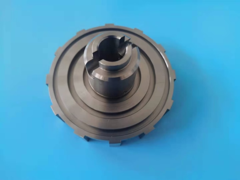
How CNC lathe machine operation removes material
In CNC lathe machine operation, the workpiece rotates and the cutting tool stays largely still in Z. The spindle holds the part in a chuck, collet, or between centers. A turret carries the tools and indexes them into position. The controller reads G-code and moves the carriage along Z and the cross slide along X, so the tool follows a path the programmer defined.
Only one point of the tool touches the part at a time. That is the core difference from milling, where a multi-flute cutter sweeps a wide arc. Single-point turning produces a continuous chip, and chip control becomes a real process variable.
Surface speed is set by diameter. A part at Ø100 mm spinning at 800 rpm runs at roughly 251 m/min at the surface; the same rpm on a Ø20 mm feature gives only 50 m/min, which is far too slow for aluminum. Constant surface speed mode lets the controller raise rpm as the tool moves toward center. That is why a facing pass sounds different at the rim than near the axis.
Feed, depth of cut, and tool nose radius set the theoretical surface finish. A 0.8 mm nose radius at 0.15 mm/rev gives a smoother profile than a 0.4 mm radius at the same feed, but it also pushes the tool harder on slender parts. The trade-off shows up as chatter, not as a number on a drawing.
Two-spindle, Swiss, and mill-turn variants
A standard 2-axis lathe turns outside diameters, faces, and bores. Add a Y axis or a sub-spindle and the machine can cut flats, cross-holes, and the back side of the part without a second setup. GreatLight runs 16 mill-turn centers alongside 12 four-axis mills and 16 simultaneous 5-axis machining centers, so the choice between turning and milling is made on part geometry, not on what happens to be free.
Swiss-type lathes feed bar stock through a guide bushing and cut close to the support point. They hold tight tolerance on long, thin shafts where a conventional chuck would let the part deflect. The trade-off is diameter range and the cost of guide bushings sized to the bar.
Mill-turn machines are the practical answer when a part is mostly cylindrical but needs a few off-axis features. One setup means one datum, and one datum means fewer stacked tolerances. On a part with a Ø0.02 mm true-position callout on four bolt holes, that difference decides whether the print is meetable.
Pick the simplest machine that holds the print. A 2-axis lathe with a bar feeder is cheaper per part than a mill-turn center, and it is often faster. Complexity only pays when it removes a second operation.
What has to be right before the cycle starts
Setup is where most scrap is born. The operator mounts the jaws, bores them true if the job needs it, and sets tool length and wear offsets. A wrong offset of 0.05 mm is invisible in the code and obvious in the first article.
Workholding choice drives accuracy. A three-jaw chuck is fast but repeats to about 0.05 mm. A collet holds closer, and soft jaws bored in place on the machine give the best roundness for a specific diameter. Between centers with a face driver holds concentricity across a shaft but needs center holes.
The first article gets measured, not eyeballed. On a turned part we check the OD, the bore, the length, and any runout callout, then adjust offsets before the run continues. GreatLight inspects 100% of parts before shipment, with raw material verification, in-process monitoring, and a final check; reports are available on request.
Thermal growth matters on long runs. A spindle that has been running for two hours is not the same machine that cut the first part. On a ±0.005 mm job with hundreds of pieces, letting the machine warm up before the first article is cheaper than sorting parts afterward.
Insert geometry and what it does to the cut
Turning inserts are graded by substrate, coating, and geometry. A positive rake insert cuts freely and suits aluminum and stainless. A negative rake insert is stronger and takes heavier depth of cut on steel, at the cost of higher cutting force.
Coating matters more than most drawings suggest. TiAlN handles steel and stainless at higher temperatures; uncoated polished inserts prevent built-up edge on aluminum and on gummy plastics. Running the wrong grade shows up as short tool life or a smeared finish, not as a dimensional error, so it is easy to miss until the parts are inspected.
Boring bars are the weak link on internal features. A bar with an L/D of 4:1 is rigid; past 6:1 it deflects and chatters. The usual fixes are a carbide bar instead of steel, a smaller depth of cut, or a change in spindle speed. If the bore tolerance is tight and the reach is long, the process may need to be rethought rather than tuned.
Threading is a synchronized operation. The controller must match spindle rotation to Z travel exactly, or the pitch drifts. On coarse threads in stainless, multiple light passes beat one heavy pass for both finish and insert life.
Material behavior on a lathe
Aluminum 6061, 2024, 6082, and 7075 turn easily at high surface speed. They also produce long stringy chips that wrap around the tool if the feed is too light. Increasing feed per revolution breaks the chip, which sounds backwards but works.
Stainless 303 and 316 behave differently. 303 is free-machining and turns like a dream. 316 work-hardens, so a tool that rubs instead of cuts will harden the surface and destroy the next pass. Keep the feed up and never dwell.
Titanium Ti-6Al-4V and Inconel sit at the hard end. Heat stays in the cutting zone instead of leaving with the chip, so tool life is short and coolant strategy matters. These materials are usually run at low surface speed with high-pressure coolant.
Plastics such as POM, PEEK, and PC need sharp, polished tools and generous clearance. They expand with heat, so a dimension measured right off the machine can change after the part cools. Let it stabilize before the final check.
Which turning setup fits the part
Match the geometry to the machine before quoting.
| Part feature | Best setup | Watch out for |
|---|---|---|
| Straight shaft, OD and threads | 2-axis lathe with bar feeder | Bar stock size limits diameter |
| Long slender shaft, L/D over 8 | Swiss-type with guide bushing | Bushing must match bar diameter |
| Cylindrical body with cross-holes | Mill-turn or Y-axis lathe | Live tooling adds cycle time |
| Both ends machined, tight coaxiality | Sub-spindle or twin-spindle lathe | Transfer accuracy affects runout |
| Flats, pockets, deep 3D contours | 5-axis mill | Turning cannot reach the feature |
| Ø400 mm disc, one face | Lathe with Ø400 mm rotary table | Chuck jaws must clear the swing |
When turning is the right call
If the part is mostly cylindrical and the tolerances live on diameters, coaxiality, or threads, turn it. If the critical features are flats, pockets, or 3D contours, mill it. If the part needs both, use a mill-turn center and hold one datum instead of two setups.
Common questions
What is the difference between a CNC lathe and a CNC mill?
A lathe rotates the workpiece and moves a single-point tool. A mill rotates the tool and moves the workpiece. Turning suits diameters, threads, bores, and faces; milling suits flats, pockets, slots, and contoured surfaces.
Many parts need both. A mill-turn center does both in one setup, which removes a re-chucking error and usually shortens the total cycle.
How accurate is CNC lathe machine operation?
At GreatLight, turned parts hold ±0.005 mm (±0.0002 in) on diameters under normal conditions. That figure depends on part rigidity, material, and feature length.
A short, stiff feature in aluminum can be held tighter than a long slender shaft in titanium. Bring the print and we will tell you which callouts are realistic before the job runs.
Which materials can be turned?
We turn aluminum 6061, 2024, 5052, 6063, 6082, and 7075; stainless 303, 304, 316, 316L, 17-4PH, and 440C; steels 1018, 1045, 4130, 4140, and 4340; copper and brass alloys such as C36000; titanium TA1, TA2, and TC4; Inconel; magnesium AZ31B and AZ91D; and plastics including POM, PEEK, PC, and ABS.
Very abrasive or very gummy grades may need a specific insert grade and a slower surface speed, which changes cycle time rather than feasibility.
Can a lathe cut off-axis holes and slots?
Not on a 2-axis machine. Those features need live tooling with a Y axis, a sub-spindle, or a separate milling operation.
If a part has four cross-holes at a tight true-position tolerance, a mill-turn center is usually cheaper than two setups on two machines, because the second setup adds a datum and a re-chucking error.
How long does a turned job take from quote to delivery?
Quotation and a free DFM analysis come back within 12 hours. Production can start within 24 hours of approval, and parts typically ship in 3–5 days.
There is no minimum order quantity. We run from a single prototype up to 10,000+ part runs, so a first article and a production batch use the same process.
Can you machine parts with a finish requirement?
As-machined turning lands around Ra 1.6–3.2 μm. With the right insert and parameters, Ra 0.8–1.6 μm is routine, and fine turning can reach Ra 0.2–0.8 μm.
Beyond that, features like anodizing, electroless nickel, bead blasting, or polishing are handled as a finishing step after turning.
Send the drawing, get a turning plan
Upload your part and we will confirm the setup, the tolerance you can actually hold, and the cost per piece.
12-hour quoteFree DFM analysis100% inspection
More from the shop floor
We publish setup notes, tooling trials and inspection data from the factory floor.











