
What Is a CNC Machined Brake Track?
A brake track is the friction surface a pad, shoe or caliper clamps against to slow a rotating or sliding part. This page explains how that surface is cut, which materials hold up, and the tolerance and finish numbers that decide whether a track works or glazes over in service.
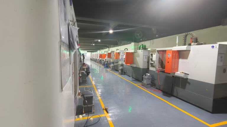
How a CNC machined brake track works
A brake track is the running surface where friction is generated. On a disc brake it is the swept band on each side of the rotor. On a drum brake it is the inner face of the drum. On rail, crane and conveyor systems it can be a separate steel plate or rail head that a shoe presses against. The track is not the pad and not the caliper. It is the surface the pad wears against, and it carries every bit of the heat and shear that braking produces.
The mechanism is simple to state and hard to control. Kinetic energy turns into heat at the interface. That heat spreads into the track, the pad and the air. If the track is not flat, contact pressure concentrates in a few spots, those spots run hot, and the pad material changes there first. Once a spot gets hot enough it can glaze, crack or transfer a lump of pad material onto the track. From then on the brake pulses and the friction coefficient drifts.
CNC machining matters because it sets the starting geometry. Turning and milling control three things the pad can feel: flatness of the swept band, surface roughness, and the runout of the track relative to the hub or shaft. Get those three right and the pad beds in evenly. Get them wrong and no pad compound will save the brake.
The track is also a wear part. It is expected to lose 0.1 to 0.5 mm of thickness over its life, depending on load and duty cycle. So the drawing needs a minimum thickness and a wear limit, not just a nominal dimension. Machining leaves enough material above that limit for the service interval the customer expects.
- 1Flat band, even pressureA flat track spreads clamp load across the whole pad.
- 2Right roughness, right bed-inToo smooth and the pad never seats; too rough and it eats the pad.
- 3Low runout, low pulsationRunout shows up as brake judder at the lever or pedal.
Which materials suit a machined brake track
Most brake tracks are made from cast iron, medium-carbon steel or stainless steel. Gray cast iron (similar to the 1018 to 1045 family in machinability) conducts heat well and damps vibration, which is why it still shows up on heavy vehicles. It is easy to turn and holds a flat face with little springback. The downside is corrosion. Bare iron tracks rust in humid storage, so they usually need a protective film or a coating that stops before the swept band.
Medium-carbon steel such as 1045 or 4140 is the workhorse for industrial brakes, press brakes, winches and rail components. It takes heat, it is cheap, and it can be through-hardened or induction-hardened to resist wear. Machining a hardened track is a different job from machining a soft one. If the track is hardened before finishing, we grind or hard-turn it. If it is hardened after finishing, we leave 0.2 to 0.4 mm of stock and control distortion in heat treat.
Stainless steel grades 420, 431 and 440C are common where corrosion resistance matters more than raw heat capacity. 17-4PH (SUS630) is used on aerospace and medical brake elements because it can be aged to high hardness while staying reasonably corrosion resistant. Stainless machines slower, generates more tool wear, and can work-harden if the feed is too light. On thin tracks it also moves more with heat, so the flatness spec has to account for thermal growth.
Titanium and aluminum appear in lighter duty. Aluminum 6061-T6 and 7075 are used on bicycle rims and some low-energy test rigs. They machine fast but they wear quickly and they conduct heat away from the pad faster than steel, which shortens pad life. For high-energy braking, aluminum is usually a carrier or a hub, not the friction surface.
Material choice also drives the finishing route. Cast iron and carbon steel can be turned to a fine finish and left bare. Stainless often gets bead blasting or a light passivation. Aluminum tracks usually get hardcoat anodizing, but the swept band is often masked so the pad sees bare metal or a controlled coating, never a thick oxide layer that would flake.
Flatness, runout and finish numbers that matter
The numbers on a brake track drawing should tell the machinist what the pad will feel. Flatness of the swept band is the first one. For automotive and light industrial rotors we hold flatness within 0.005 mm on the friction face. That is tight, and it is deliberate: any bow in the band becomes a high spot once the brake heats up.
Runout relative to the mounting bore is the second number. Lateral runout on a rotor is typically held under 0.03 mm, and for precision instrument brakes it can be tighter. Runout causes thickness variation as the rotor turns, and thickness variation causes pulsation. A track can be perfectly flat and still pulse if it is not square to the shaft.
Surface roughness controls bed-in. A turned finish in the range of Ra 0.8 to 1.6 μm gives the pad something to bite into without tearing it up. Finer than Ra 0.2 μm and the pad may never fully seat, which shows up as a long, weak bed-in period. Coarser than Ra 3.2 μm and the track acts like a file, wearing the pad and generating dust fast.
Thickness tolerance and parallelism come next. A rotor with 0.01 mm of thickness variation will pulse, even if both faces are individually flat. We measure both faces and the parallelism between them, not just the outside diameter.
Finally there is surface integrity. Turning can leave a torn or smeared layer on soft steel. That layer looks fine on a bench and fails in service. A light finishing pass with a sharp tool and a positive edge geometry removes it. If the drawing calls for a ground finish, we grind after heat treat and re-check flatness on a surface plate or a CMM.
- 1Flatness 0.005 mmOn the swept friction face, measured after final operation.
- 2Runout under 0.03 mmLateral runout relative to the mounting bore or shaft.
- 3Ra 0.8–1.6 μmA working turned finish that lets the pad bed in.
- 4Parallelism 0.01 mmBetween the two friction faces of a rotor.
Turning, milling and grinding: choosing the process
Round tracks, rotors and drums are turned. The part spins and a single-point tool sweeps the friction face. Turning gives a continuous cut, so the surface is uniform and the flatness is easy to hold. On a 4000 mm maximum processing size lathe we can handle large drums and flywheel-type tracks in one setup, which keeps runout low because there is no re-chucking error.
Flat tracks, rail plates and caliper mounting faces are milled. A face mill or a fly cutter produces the swept band, and the same setup cuts the mounting holes and the locating features. That is the advantage of milling: geometry and datums come off one setup, so the track is square to the bolt pattern by construction rather than by inspection.
When the drawing demands a very fine finish or the part is hardened, we grind. Grinding removes the smeared layer that turning can leave and gives a controlled Ra with almost no residual stress. It is slower and it costs more, so we only use it where the drawing or the duty cycle requires it. A press brake die track that runs at low speed does not need a ground face. A high-speed rotor does.
Five-axis machining is used when the track is not a simple surface: tapered drums, angled rail heads, or a brake track blended into a hub or a bracket. We run 16 simultaneous 5-axis centers, and one setup can cut the track, the mounting flange and the oil or cooling passages. Fewer setups means fewer datum shifts and less stack-up error.
For prototypes, mill-turn centers are often the fastest route. A single bar goes in, the track and the hub come out, and the customer gets a part in days rather than weeks. For production, the same geometry may move to a dedicated turning cell with a purpose-built fixture so cycle time drops.
- 1Turn round tracksRotors, drums and flywheel faces; one setup keeps runout low.
- 2Mill flat tracksRail plates and brackets; datums cut in the same setup.
- 3Grind when hard or fineHardened tracks and Ra below 0.4 μm get a ground face.
- 45-axis for blended shapesTapered drums and tracks merged into hubs or brackets.
When CNC machining is the wrong answer
CNC machining is not always the cheapest way to make a brake track, and it is not always the right one. If the track is a simple flat plate in high volume, stamping or laser cutting plus a finish pass may cost far less. Machining wins when the geometry is complex, the tolerance is tight, or the quantity is low. It loses when the part is a flat washer with a generous tolerance and the annual volume is in the hundreds of thousands.
Cast iron rotors are often cast close to shape and then only the friction faces are machined. Trying to cut the whole rotor from bar stock would waste material and time. The right approach is casting plus finish machining, and we say so when the drawing points that way.
Very large tracks hit a machine limit. Our maximum processing size is 4000 mm, with a 4000 × 400 × 150 mm travel on the largest mill. Beyond that, the part has to be built in segments and joined, or made by a different process. We tell customers this at the quote stage, not after they place an order.
Thin, flexible tracks are another boundary. A track less than about 3 mm thick in steel will deflect under clamping and chatter during turning. It can still be machined, but it needs a support fixture, light passes and a stress-relief step between roughing and finishing. If the design allows, adding a rib or a thicker hub section makes the part cheaper to machine and more stable in service.
- 1High-volume flat platesStamping plus a finish pass usually beats full machining.
- 2Cast rotorsMachine the friction faces only; leave the casting as cast.
- 3Over 4000 mmSegment the part or choose a different process.
- 4Under 3 mm thickExpect a fixture, light passes and stress relief.
Brake track material and process selection
Pick the row that matches your duty cycle, then confirm the finish callout.
| Material | Typical use | Machining route | Finish target |
|---|---|---|---|
| Gray cast iron | Heavy vehicle rotors, drums | Turn friction faces only | Ra 1.6–3.2 μm |
| 1045 / 4140 steel | Industrial, press brake, winch | Turn, harden, grind | Ra 0.8–1.6 μm |
| 420 / 431 stainless | Corrosion-prone outdoor brakes | Turn, stress relieve, finish | Ra 0.8–1.6 μm |
| 17-4PH (SUS630) | Aerospace, medical brake elements | Turn, age, grind | Ra 0.2–0.8 μm |
| 6061-T6 aluminum | Bicycle rims, light test rigs | Turn or mill, mask swept band | Ra 0.8–1.6 μm |
| TC4 (Ti-6Al-4V) | Lightweight high-temp brakes | Turn slow, 5-axis for blends | Ra 0.8–1.6 μm |
The short version
If the track is round, tight and low volume, turn it in one setup and hold flatness at 0.005 mm. If it is flat, high volume and generous on tolerance, stamp or cast it and machine only the friction face. Choose the second route when the annual volume justifies tooling and the pad never sees more than light duty.
Questions engineers ask next
How flat does a brake track really need to be?
For automotive and light industrial rotors we hold 0.005 mm flatness on the swept band. That is tighter than most drawings ask for, and it is there to survive thermal growth. A track that is flat cold can bow once it reaches 300 °C. If your duty cycle is light, a 0.02 mm flatness callout may be enough and it will cost less to make.
Should the swept band be masked before anodizing?
Yes, on aluminum tracks. A hardcoat layer on the friction surface is brittle and can flake under pad shear. We mask the swept band so the pad sees bare or lightly finished metal. The rest of the part still gets the full coating for corrosion protection. If the customer wants a coated friction face, we discuss it before the finish operation, not after.
Can you machine a brake track that is already hardened?
Yes, up to about 45 HRC with carbide tooling, and higher with ceramic or CBN inserts. Hard turning holds flatness well and avoids the setup error of a second operation. Above that hardness, or when the drawing calls for Ra below 0.4 μm, grinding is the better route. We check the hardness spec on the drawing before quoting.
What causes brake judder on a machined track?
Judder usually comes from lateral runout or thickness variation, not from roughness. If the track is not square to the mounting bore, the pad sees a thicker and thinner section as the part turns. We measure runout against the bore and parallelism between faces, and we report both numbers so you can trace judder to the right dimension.
How thin can a steel brake track be machined?
Below about 3 mm, steel deflects under clamping and chatters during turning. It can still be done with a support fixture, light depth of cut and a stress-relief step between roughing and finishing. If the design allows a rib or a thicker hub, the part gets cheaper to machine and holds its flatness better in service.
Do you provide inspection reports for brake tracks?
Yes. Every part gets a raw material check, in-process monitoring and a final inspection before shipment, and we inspect 100% of the batch. Flatness, runout, parallelism and roughness can be reported on request, measured on a CMM, a surface plate or a profilometer. Tell us which dimensions matter and we will put them on the report.
Send us your brake track drawing
We review the drawing, flag the tolerances that will drive cost, and come back with a quote and a free DFM analysis. No minimum order quantity, from one prototype to a 10,000+ part run.
12-hour quoteFree DFM analysis100% inspectionNDA on request
More from GreatLight
We publish setup notes, tooling trials and inspection data from the factory floor.











