
What Is CNC Machined? How a Program Becomes a Metal Part
CNC machining is a subtractive process: a computer-controlled tool removes material until the part matches a CAD model. This page explains the mechanism, the machine types, and the cases where machining is the wrong choice.
In this article
- 1
- 2
- 3
- 4
- 5
- 6
- 7
What Is CNC Machined: The Cutting Loop Explained
What is CNC machined comes down to a closed loop. A CAM programmer turns a 3D model into G-code, which is a list of coordinates and feed rates. The machine controller reads that list and drives servo motors on each axis. The spindle spins a cutter, the axes move the tool or the workpiece, and material comes off as chips. No hand wheel decides where the tool goes.
The loop closes at the scale of milliseconds. Encoders on each axis report actual position back to the controller, which compares it with the commanded position and corrects the motor. That feedback is why a machined face can hold ±0.005 mm on a good day. The cutter never "knows" the shape of your part; it only follows the path the programmer gave it.
Subtractive means material is removed, not added or formed. That matters for two reasons. First, the starting stock must be larger than the finished part, so you pay for metal you will cut away. Second, internal features are reachable only if a tool can physically get there. A deep pocket with a sharp internal corner is a drawing problem before it is a machining problem.
The cutting itself is a controlled fracture. Each tooth of the cutter shears a chip off the workpiece. Heat goes into the chip, the tool, and the part in that order. Coolant or air blast carries heat away and clears chips. If chips are not evacuated, they get re-cut, which dulls the tool and spoils the finish.
- 1CAM outputG-code defines tool path, feed, and speed.
- 2Servo feedbackEncoders correct axis position in real time.
- 3Chip formationEach tooth shears a chip; heat leaves with it.
- 4Stock allowanceStarting block is always bigger than the part.
3-Axis, 4-Axis, and 5-Axis: What Changes
A 3-axis mill moves X, Y, and Z. The tool always points down. That is fine for plates, housings, and parts with features on one or two faces. Setup is simple: clamp the stock, touch off the corner, run the program. Most of the world's machined parts are still made this way.
A 4-axis machine adds rotation around one axis, usually A. The part indexes to a new face while staying clamped. You get four sides in one setup instead of four separate fixtures. Shafts with flats, cross-drilled holes, and slot patterns become practical.
A 5-axis machine adds two rotational axes, so the tool can approach from nearly any direction. Contoured surfaces, undercuts, and deep cavities that need a short, rigid tool are the payoff. The trade-off is programming time and machine cost. On a 3-axis machine, a complex part may need several fixtures; on a 5-axis center it may run in one setup.
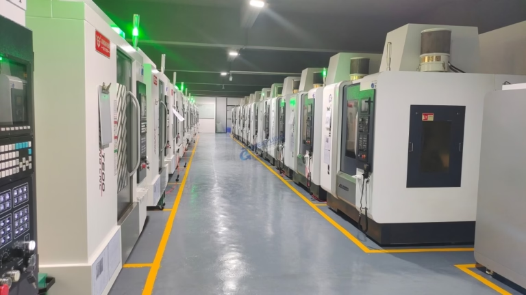
At GreatLight we run 16 simultaneous 5-axis centers, 12 four-axis mills, 27 three-axis machines, and 16 mill-turn centers among 127 machines. We pick the machine by feature access and tolerance, not by what is newest. A simple bracket does not need five axes.
Where Machining Stops Being the Right Answer
Machining wins on accuracy and material choice. It loses on hollow, thin-walled, and very high-volume parts. If a part is mostly empty inside, you cut away most of the stock and pay for chips. That is when casting, forging, or additive processes start to make sense.
Tool access sets a hard boundary. A cutter has a diameter, and its corner has a radius. An internal corner sharper than that radius cannot be cut without electrical discharge machining or a broach. Deep pockets need a long tool, and a long tool deflects. A depth-to-diameter ratio beyond about 4:1 usually forces a larger cutter, a step-down strategy, or a different process.
Surface finish is a trade, not a switch. As-machined surfaces land around Ra 1.6–3.2 μm. Finer passes reach Ra 0.8–1.6 μm. Getting to Ra 0.2–0.8 μm takes slow finishing passes, sharp tooling, and stable fixturing, which costs cycle time.
Volume changes the math too. Machining has almost no tooling cost, so one prototype and 10,000 parts use the same program. Die casting needs a mold but has a much lower piece price. The crossover depends on geometry and material, and it is worth checking both quotes before committing.
- 1Good fitTight tolerances, low to mid volume, hard materials.
- 2Poor fitLarge hollow shells, very high volume, sharp internal corners.
- 3Tool radiusInternal corner cannot be sharper than the cutter.
- 4Depth ratioPast ~4:1, deflection and chatter become likely.
How Material Choice Changes the Cut
Aluminum 6061 cuts fast and holds tolerance well. It is the default for prototypes and fixtures. 7075 is stronger but gummier, so it needs sharper tools and lighter chiploads. Plastics like POM and PEEK cut cleanly but move with heat, so roughing and finishing passes are separated to let the part cool.
Stainless 303 and 304 work-harden if the tool rubs instead of cuts. The fix is a positive rake and a feed that keeps the tooth biting. 17-4PH in the H900 condition is common for medical and aerospace parts; it needs carbide and slower surface speeds. Titanium Ti-6Al-4V is worse: low thermal conductivity keeps heat in the cutting zone, so coolant delivery and tool life dominate the process plan.
Inconel and magnesium sit at opposite ends. Inconel is abrasive and slow, with tool wear driving cost. Magnesium AZ31B and AZ91D cut quickly but the chips are flammable, so chip control and coolant rules are strict.
The material list we hold covers 6061, 2024, 5052, 7075, 303, 316L, 17-4PH, 1018, 4140, 4340, C360 brass, Ti-6Al-4V, and engineering plastics. If your alloy is not on that list, say so early. Substituting a similar grade can change strength, corrosion behavior, or biocompatibility.
Reading a Tolerance Callout Like a Machinist
A tolerance is a range, and the range costs money as it narrows. General dimensions at ±0.1 mm are routine. Critical fits at ±0.005 mm require stable fixturing, temperature control, and in-process checks. Putting a tight tolerance on a non-functional dimension adds cost for nothing.
Datum structure drives the setup. If the drawing names A, B, and C datums, the machinist builds the fixture around them. If the datums are vague, the first article may pass inspection and still fail assembly, because two shops measured from different references.
Geometric callouts matter as much as size. Flatness, perpendicularity, and true position control how the part behaves once it is bolted to something else. A shaft can be perfectly round and still fail if it is not straight.
GreatLight inspects 100% of parts before shipment, with raw material checks, in-process monitoring, and final inspection. Reports are available on request. That matters most on the first article, where the goal is to confirm the process, not just to pass the part.
From Cutting Marks to a Finished Surface
Machining leaves tool marks. Whether they matter depends on the function. A sealing face needs a controlled finish. A cosmetic panel needs a uniform one. An internal bracket often needs nothing.
Bead blasting hides tool marks and gives a matte look. Tumbling and brushing soften edges. Polishing reaches a reflective surface. Anodizing adds corrosion resistance and color on aluminum; hardcoat anodizing adds wear resistance. Electroless nickel, zinc, silver, and gold plating cover electrical and corrosion needs. Powder coating and black oxide are options for steel.
Laser marking handles part numbers and traceability. Minimum character height is 1.5 mm, so plan the marking area before the geometry is frozen. A marking field placed on a curved or angled surface is a common late-stage problem.
Finish and tolerance interact. A heavy coating can shift a dimension by more than the tolerance. If a part is anodized after machining, say so at quoting so the machinist can leave stock for the coating.
Machining vs Other Processes: Quick Check
Use this to decide whether to request a machining quote or a different process.
| Process | Best for | Watch out for | Typical tolerance |
|---|---|---|---|
| 3-axis CNC | Plates, housings, 1–2 face features | Multiple setups on complex parts | ±0.01 mm and tighter |
| 5-axis CNC | Contoured surfaces, undercuts, one-setup parts | Higher programming and machine cost | ±0.005 mm |
| CNC turning | Shafts, bushings, round parts | Off-axis holes need a second op | ±0.01 mm |
| Die casting | High volume, thin walls | Mold cost and lead time | ±0.05 mm, then machined |
| 3D printing | Complex internal channels, fast prototypes | Weaker material, rougher finish | ±0.1 mm and looser |
| Sheet metal | Enclosures, brackets, flat parts | Limited 3D geometry | ±0.1 mm |
When to Choose Machining
If your part is solid, needs tight fits, and the volume is one to a few thousand, machine it. If it is mostly hollow, thin-walled, and you need tens of thousands, cast or print it first and machine only the critical faces.
Common Questions About CNC Machining
What does CNC actually stand for?
Computer Numerical Control. The machine follows a numeric program rather than a hand wheel. The program is generated from a CAD model by CAM software.
The operator still matters. They set the fixture, load tools, verify offsets, and watch the first part. The controller handles repeatability, not judgment.
Is CNC machining only for metal?
No. Plastics such as ABS, PC, POM, PEEK, and PA are machined daily. Composites like carbon fiber can be machined with the right tooling and dust control.
Material behavior changes the parameters, not the principle. Plastics cut faster but move more with heat, so finishing passes are often separated from roughing.
How tight a tolerance can machining hold?
GreatLight works to ±0.005 mm (±0.0002 in) on critical features with the right setup and inspection. That is not a default for every dimension.
Tightening a tolerance narrows the process window and adds inspection time. Apply it only where the function needs it.
What is the difference between CNC milling and turning?
Milling spins the tool and moves it against a stationary workpiece. Turning spins the workpiece against a stationary tool. Round parts belong on a lathe; prismatic parts belong on a mill.
Mill-turn centers combine both, so a part can be turned and milled in one setup. That reduces handling error on complex shafts and fittings.
Why does my part need a radius in the internal corner?
Because the cutter is round. A rotating tool leaves its own radius in any corner it cuts. A sharp internal corner would require a square tool, which cannot spin.
If the design needs a sharp corner, plan for EDM or a broach, or add a relief groove so the radius does not interfere with the mating part.
How do I keep my design confidential?
Uploads are handled as secure and confidential, and a non-disclosure agreement is available on request. We can review it before files are shared.
For early-stage work, send simplified geometry or a marked-up drawing rather than the full model, then release the detailed files after the NDA is in place.
Send Your CAD and Get a Machining Quote
Quotation and free DFM analysis within 12 hours, with no minimum order quantity from one prototype to 10,000+ part runs.
12-hour quote100% inspectionNDA on request
More From GreatLight
We publish setup notes, tooling trials and inspection data from the factory floor.











