
What Is MLA Used For in CNC Machine Control?
MLA is the machine location axis, the fixed reference point a CNC control uses to know where every axis really is. This page explains the mechanism, where it stops mattering, and how it relates to G54 work offsets and 5-axis kinematics. It is written for engineers and buyers who need to judge setup risk, not for machine builders.
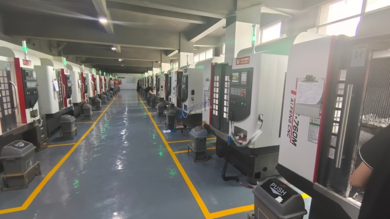
What is MLA used for in CNC machine control
MLA stands for machine location axis, sometimes written as machine zero. It is the absolute reference point built into the machine tool itself, not into the part. Every linear axis and every rotary axis has a physical home position, and the control measures all movement from that point. When the controller reports Z at -412.500 mm, that number means 412.5 mm below machine zero, not below the top of your workpiece.
The distinction matters because operators spend their day in work coordinate systems such as G54 through G59. Those offsets are shifts stored in the control, and each one tells the machine where the part sits relative to the machine location axis. Change the fixture, and you change the offset. The MLA underneath does not move.
So the honest answer to what is MLA used for in cnc machine work is this: it is the datum the control trusts when nothing else is trustworthy. Tool length offsets, rotary centerlines, pallet positions and probe results all resolve back to it. If that reference drifts, every offset built on top of it drifts with it.
Four jobs the machine location axis does every shift
The first job is defining travel limits. Each axis has soft limits set relative to machine zero, and the control stops motion before the ball screw or linear guide reaches its mechanical end. On a machine with 4,000 × 400 × 150 mm travel, those limits are fixed numbers in the parameters. They are not something the programmer sets per job.
The second job is supporting tool length and diameter offsets. A tool offset only means something once the control knows where the spindle nose is in absolute space. Touch off a tool on a setter, and the stored length is a distance from the machine reference. Swap the toolholder and the number changes, but the datum does not.
The third job is anchoring rotary axes. On a 5-axis center with a Ø400 mm rotary table, the control needs the exact position of the trunnion and table centerlines relative to machine zero to run kinematic transformations. Get those values wrong and the tool tip misses even when every linear axis is correct.
The fourth job is drift and compensation reference. Thermal growth moves a spindle several microns over a long cut. Ball screw pitch error maps, straightness maps and volumetric compensation all store corrections against the machine reference. That is what lets a shop hold ±0.005 mm through a full day of roughing and finishing.
When MLA accuracy stops being the limiting factor
It is easy to over-credit the machine zero point. In most production setups, the dominant error is not the datum, it is the fixture. A vise jaw that lifts 0.02 mm under clamping pressure will hurt a bore position far more than a reference point that repeats to a micron. Check the fixture before you blame the machine.
Workholding repeatability is the next limit. If a pallet is loaded by hand and located on dowel pins with 0.01 mm clearance, the part moves every time, and the offset must be probed again. On a tombstone with hydraulic clamping and a repeatable receiver, the same offset can run for weeks.
Material behavior sets another ceiling. Aluminum 6061 and 7075 move little after machining. Thin-wall titanium and Inconel parts move a lot, and no reference point fixes that. Stress relief, restroughing passes and slower finishing feeds do.
Machine geometry is the last one. A worn linear guide or a spindle that tilts under load produces errors the control cannot see. Volumetric compensation helps with repeatable geometric error. It does nothing for a bearing that is failing. That is a maintenance problem, not a datum problem.
How MLA works on simultaneous 5-axis machines
On a 3-axis mill, the relationship between machine zero and the part is simple: three offsets and a tool length. On a 5-axis machine, two rotary axes sit between the reference point and the cutting edge. The control must convert a tool tip position and tool axis vector into commands for five motors at once.
That conversion depends on stored kinematic values: pivot distances, rotary centerline offsets, and the distance from the table surface to the rotary axis. These are measured at installation and periodically rechecked. A trunnion centerline that is off by 0.05 mm will throw off a tilted surface even though the linear axes are perfect.
This is why aerospace impellers, blisks and complex housings are so sensitive to machine setup records. Cutting a ruled surface at 45° tilt uses both rotary axes plus three linear moves. Every one of those commands resolves back to the machine reference.
For shops running 16 simultaneous 5-axis machining centers, the practical control is a documented calibration schedule and a warm-up cycle before the first tight-tolerance part of the day.
Machine zero vs work offset: which one you actually touch
| Item | Machine location axis | Work coordinate system |
|---|---|---|
| Set by | Machine builder at installation | Operator or programmer per job |
| Stored in | Machine parameters | G54–G59 offsets |
| Changes when | Servo or encoder is replaced | Fixture or part changes |
| Used for | Travel limits, kinematics | Part datum and toolpaths |
| Typical value | Fixed absolute position | Shift of a few mm to 500 mm |
| Who checks it | Maintenance and calibration | Setup operator |
| If it drifts | Every job on the machine shifts | One job shifts |
| Recovery | Re-home and re-calibrate | Re-probe and reset offset |
The practical takeaway
If your parts are drifting job to job, fix the work offset and the fixture. If every job on the machine is off by the same amount, the machine reference is the problem. Chase the right one.
Common questions
Is MLA the same as machine home?
In everyday shop talk, yes. Home is the position the axes return to when you reference the machine, and that position defines the machine location axis.
Some builders put home at one end of travel rather than at the exact zero of the coordinate system. The parameter table will tell you which convention your machine uses.
Do I ever program to machine zero directly?
Rarely, and only for setup work. Programs normally run in a work coordinate system so the same code can move between machines.
Direct machine coordinates are useful for tool changers, pallet positions and probe calibration macros.
What happens if the MLA is wrong?
Every offset on that machine is wrong by the same amount. A 0.1 mm error in the reference shows up as a 0.1 mm shift on every part, in the same direction.
Re-reference the axes and recheck the kinematic values before running production.
Does MLA affect surface finish?
Only indirectly. It does not change cutting parameters or tool condition.
It matters on 5-axis work because wrong rotary centerlines produce faceting and mismatch on blended surfaces.
How often should machine zero be verified?
After any crash, servo replacement, or encoder battery change, and on a routine calibration interval for tight-tolerance work.
For shops holding ±0.005 mm, a documented schedule beats fixing problems after a rejected lot.
Can software fix a bad reference point?
No. Compensation tables correct repeatable geometric error, not a wrong datum or a worn guide.
Fix the mechanical cause first, then apply compensation.
Send us your drawing and we will flag the setup risk
Upload a STEP file and we return a quotation with free DFM analysis within 12 hours. Prototypes and 10,000+ part runs both run on the same 127-machine floor.
12-hour quote±0.005 mm100% inspection
More CNC process notes
We publish setup notes, tooling trials and inspection data from the factory floor.











