
Which Coordinate System Is Used These CNC Machine Types?
Every machine tool moves on some coordinate frame, and that frame decides how many setups a part needs, where tolerance stacks up, and what you pay per piece. This guide compares the frames behind these cnc machine types: 3-axis, 4-axis, 5-axis, turning centers, mill-turn centers and EDM. Read it and you can judge which machine a drawing should go on.
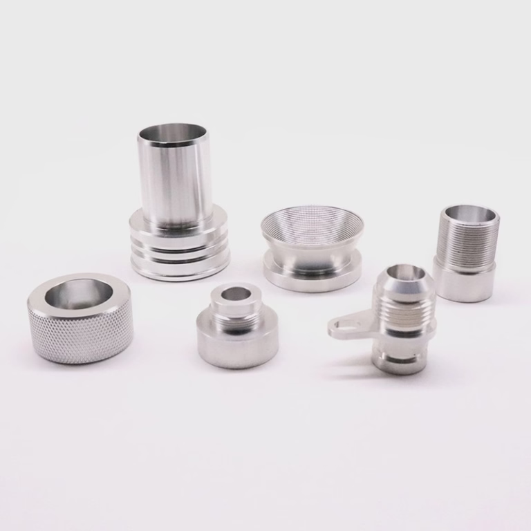
Coordinate Systems Across These CNC Machine Types
Axes, work envelope and best-fit parts for each machine type.
| Machine type | Coordinate system | Typical axes | Best-fit parts |
|---|---|---|---|
| 3-axis mill | Cartesian X, Y, Z | 3 linear | Prismatic plates, pockets, flat faces |
| 4-axis mill | Cartesian plus A rotation | 3 linear + 1 rotary | Shafts, gear brackets, multi-face holes |
| 5-axis mill | Cartesian plus two rotary axes | 3 linear + 2 rotary | Impellers, medical implants, complex contours |
| Turning center | Polar (X radius, Z length) | 2 linear | Shafts, bushings, threaded fittings |
| Mill-turn center | Cartesian plus polar, one platform | 3 linear + rotary + spindle | Valve bodies, hydraulic manifolds |
| EDM (sinker / wire) | Cartesian, tool offset on Z or U/V | 3 to 5 linear | Hardened dies, sharp internal corners |
Cartesian Frames on 3-Axis and 4-Axis Mills
A 3-axis machining center is the reference point for every other machine on this list. The part sits on the table, and the tool moves in X, Y and Z. That is the Cartesian system, and it maps one-to-one onto the drawing dimensions an engineer already has. When a print calls out a hole pattern at X 120 mm, Y 45 mm, the operator can read that straight into the control.
The trade-off is setups. A part with features on five faces needs five separate fixturing positions, and each reposition adds a datum shift. On a ±0.005 mm part, that shift is where most of the error budget goes. For flat plates, pockets and single-face work, though, 3-axis is fast and cheap. Our own shop runs 27 three-axis machines for exactly that reason.
A 4-axis mill keeps the same Cartesian frame and adds a rotary axis, usually A around the X axis. The part indexes between cuts instead of being unclamped and moved. A cylindrical gear bracket with four bolt faces can be finished in one setup. Datum error stops accumulating, and the operator stops re-indicating the vise.
The limit is that the rotary axis is positional, not simultaneous. It indexes to a new angle, locks, then cuts. If the surface must be swept continuously, or if the tool has to stay normal to a curved wall, you have outgrown 4-axis work.
- 1Choose 3-axis whenFeatures live on one or two faces and the print tolerance is looser than ±0.02 mm.
- 2Choose 4-axis whenFeatures wrap around a cylindrical or box part and you want one setup.
- 3Watch forRotary table capacity. Our rotary tables run to Ø400 mm.
Simultaneous 5-Axis: Two Extra Rotary Axes
A 5-axis machining center adds two rotary axes to the Cartesian frame, usually A and C on a trunnion table or a swivel head. The difference from 4-axis is not the count of axes. It is that all five move at once, so the tool tip follows a path while the table tilts underneath it.
That matters because tool orientation becomes a machine variable. On a deep cavity, you can tilt the tool away from the wall so a shorter, stiffer cutter reaches the floor. On an impeller, you can keep the flank of the cutter tangent to the blade surface through the whole pass. Surface finish improves without a polishing step, and you can hold Ra 0.8–1.6 μm off the machine on many aluminum parts.
The cost side is real. Programming takes longer, and a post-processor that does not match the machine kinematics will produce gouges that no simulation catches until the part is cut. Fixturing also changes: on a trunnion you often hold the part in a dovetail block or a self-centering vise rather than a plate full of clamps, because clamps block the rotary travel.
We run 16 simultaneous 5-axis machining centers, mostly for aerospace brackets, medical housings and parts with undercut geometry. If a part has three or more angled faces that must meet a tight true-position callout, 5-axis is usually the cheaper route even at a higher hourly rate, because it removes two or three setups and the inspection that goes with them.
- 1Choose 5-axis whenAngled faces, undercuts, or continuous curved surfaces dominate the part.
- 2Skip 5-axis whenA 3-axis machine with two setups can hit the tolerance in less time.
- 3Plan forLonger CAM time and a verified post-processor before the first cut.
Turning Centers and Mill-Turn: Polar and Hybrid Frames
A CNC lathe does not use X, Y and Z in the same way. The part spins on the spindle axis, and the turret moves in X and Z. X is programmed as a radius, not a diameter, in most controls. That is a polar adaptation of the Cartesian idea, and it is why lathe prints are dimensioned on the centerline.
Radial features are the natural output: turned diameters, faces, grooves, threads and chamfers, all concentric to one axis. If your part is a shaft, a bushing or a threaded fitting, a turning center will beat a mill on cycle time almost every time. Two linear axes moving at once produce a curve; there is no third axis to coordinate.
The gap appears when a turned part also needs cross holes, flats or milled slots. On a plain lathe those features go to a second machine, and the part gets re-chucked. Every re-chuck adds runout. On a tight part, 0.01 mm of chuck error shows up directly in the concentricity reading.
A mill-turn center closes that gap. It carries the polar turning frame and a Cartesian milling frame on the same platform, sometimes with a B-axis head and a sub-spindle. The part never leaves the machine, so the turned diameter and the cross-drilled hole share one datum. We run 16 mill-turn centers and use them most for valve bodies and hydraulic manifolds, where concentricity across mixed features is the whole point.
- 1Choose turning whenThe part is primarily cylindrical and features are concentric.
- 2Choose mill-turn whenTurned and milled features must share one datum.
- 3Watch forBar capacity and sub-spindle length limits on long shafts.
EDM Frames and How Setup Count Drives Cost
EDM works on a Cartesian frame too, but the cutting action is different. A sinker burns a shaped electrode into the part along Z. A wire machine runs a thin wire through the work, with X and Y positioning the table and U and V tilting the wire for taper. The tool is not rigid in the usual sense, so it can cut shapes a rotating cutter cannot reach.
That is why EDM holds sharp internal corners. A 0.5 mm radius in a hardened die is routine on a wire machine and impossible with a 6 mm end mill. The frame is simple; the value is in the electrode and the corner geometry. For hardened tool steel above 50 HRC, EDM is often the only practical route.
Setup count is where coordinate systems turn into money. Each new frame means a new datum, a new fixture, and an inspection step. On a part with a true-position tolerance of Ø0.05 mm, three setups can eat most of the budget before a single chip is cut. Two setups on a 5-axis machine often beat five setups on a 3-axis machine on both cost and yield.
That is the judgment call this page is really about. The coordinate system is not an abstract property of the machine. It is the number of times the part gets moved, and every move is a chance to lose position.
- 1Choose EDM whenMaterial is hardened, or corners are sharper than any cutter can leave.
- 2Count your setupsEach added datum is a tolerance risk, not just an hour of labor.
- 3Plan inspectionMixed frames usually mean a CMM check against a single datum.
The Short Answer
If the features sit on one or two faces, run 3-axis or a lathe and keep the cost down. If features wrap the part, go 4-axis or mill-turn. If angled faces and curved surfaces must hold a tight true-position callout, go 5-axis, because the extra hourly rate is cheaper than three extra setups.
Frequently Asked Questions
What is the most common coordinate system in CNC machining?
Cartesian X, Y and Z. It covers 3-axis mills, and it stays underneath 4-axis and 5-axis work once the rotary axes are added.
Turning centers adapt it to a polar frame, where X is programmed as a radius around the spindle axis.
When should I choose 5-axis over 3-axis?
When the part has three or more angled faces that must meet one tight true-position callout, or when curved surfaces need continuous tool-tip contact.
If two 3-axis setups can hold the tolerance, stay with 3-axis. The CAM time and fixturing on 5-axis only pay off when setups are removed.
Do CNC lathes use the same coordinate system as machining centers?
No. A lathe uses X and Z, with X written as a radius, because the part rotates instead of the tool sweeping a Cartesian volume.
That is why lathe prints are dimensioned from the centerline, and why cross-features usually need a second operation or a mill-turn machine.
How do you keep accuracy when a part needs several setups?
We cut datum features first and reference every later setup to them, then inspect 100% before shipment with reports on request.
Where possible we consolidate setups onto 4-axis, 5-axis or mill-turn platforms so the part is not re-chucked. Every re-chuck adds runout.
Can you handle parts that need more than one coordinate system?
Yes. With 127 machines across 3 wholly-owned plants, we route turned features to a lathe or mill-turn center and milled features to a 3-axis or 5-axis center, then verify all of them against one datum.
Parts up to 4,000 mm maximum processing size are within range.
Which finishes are available after machining on different frames?
Anodizing, electroless nickel, zinc, silver and gold plating, powder coating, black oxide, bead blasting, tumbling, brushing and polishing.
Laser marking is also available, with a minimum character height of 1.5 mm.
Send the Drawing, Get a Route
Upload your CAD file and we will reply within 12 hours with a quotation and a free DFM analysis, including which machine frame we would use and why.
12-hour quote100% inspectionNDA on request
More from the shop floor
We publish setup notes, tooling trials and inspection data from the factory floor.











