
Why It Is Essential To Match Copper Block Size And Board Slot Tolerance
A copper block that sits 0.05 mm loose in its board slot will pass a bench test and fail in the field. This page is for engineers and buyers who specify press-fit heat spreaders, busbars and thermal pads. It shows which symptoms point to a copper block size board slot tolerance mismatch, and how to fix each one.
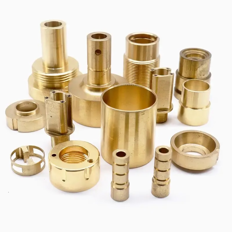
Symptom, likely cause, and what to do
Read the left column first. If two rows apply, fix the one higher up before touching the other.
| Symptom | Likely cause | Action |
|---|---|---|
| Block drops in with no drag | Block undersize by 0.03–0.08 mm | Measure both; set block at slot +0.01 mm |
| Block will not seat by hand | Block oversize or slot burr | Deburr slot, re-measure, open slot 0.02 mm max |
| Solder balls crack after cycling | Loose fit lets the block rock | Restore light press fit, then reflow |
| Board bows after reflow | Slot too tight, CTE mismatch | Open slot 0.02 mm, check copper temper |
| Hot spot above one component | Partial contact at slot base | Flatten base, check flatness 0.02 mm |
| Slot wall shows copper smear | Interference above 0.05 mm | Reduce block width, add lead-in chamfer |
| Torque drops after 100 cycles | Fretting at the slot interface | Add plating or switch to press-fit pin |
| Blocks vary lot to lot | Incoming inspection too loose | Measure each lot, not each batch |
Set the fit from the material, not the drawing
Measure the real slot spread first. If it is under 0.04 mm, put the tight tolerance on the copper block and aim for 0.01–0.03 mm of interference on C110. If the spread is wider than that, fix the slot process before you touch the block.
What the fit actually controls
A copper block does three jobs at once: it carries heat away from a hot component, it holds that component in place, and it gives the return current a short path. All three depend on how the block sits in the board slot. If the fit is loose, heat has to cross an air gap. If the fit is tight, the block loads the board and the solder joints around the slot.
The number that matters is the clearance between the block wall and the slot wall. On a press-fit copper block, that clearance usually lands between 0.01 mm and 0.04 mm of interference, depending on block width and board thickness. Below 0.01 mm the block can back out during reflow. Above 0.05 mm the slot wall starts to yield, and the copper smears.
Slot tolerance is not the same as block tolerance. A slot cut at ±0.05 mm and a block milled at ±0.05 mm can stack to 0.10 mm of worst-case mismatch. That is why a copper block size board slot tolerance check has to look at both numbers together, not one at a time.
Copper moves more than FR-4 when it heats. Over a 100 °C rise, a 30 mm copper block grows about 0.05 mm more than the same length of laminate. A fit that is correct at 25 °C can become an interference fit at 125 °C, and that is where board bow and cracked joints come from.
How a loose fit shows up as a hot spot
A gap of 0.05 mm across a 20 × 20 mm copper face is a real thermal resistor. Filled with air, that gap adds roughly 2.5 K·cm²/W to the path, which can push a 15 W component several degrees hotter than the model predicts. The thermal simulation usually assumes full contact, so the bench data looks fine and the field data does not.
Thermal interface material does not fix a bad fit. Paste, pad and liquid metal all need pressure to thin out and wet the surfaces. A block that can move in its slot cannot hold that pressure. Liquid metal helps with surface roughness, not with a block that rocks.
The hot spot usually sits over one corner rather than the whole component. That pattern means the block is touching on one edge and lifting on the other. Check the slot base flatness and the block base flatness before you change any dimension.
If the block is machined from C110 or C101, the base flatness should hold 0.02 mm across the seating face. Anything softer, such as a thin annealed strip, will conform at first and then take a set after a few thermal cycles.
How a tight fit cracks solder joints
When the block is too wide for the slot, the press force goes into the laminate. The board around the slot is thin, often 1.6 mm or less, and it does not have much stiffness left after the copper is removed. The result is local bending at reflow temperature, when the laminate is soft.
The solder balls nearest the slot see that bending as cyclic strain. A joint that survives one reflow can still crack after 500 thermal cycles between −40 °C and 125 °C. The crack starts at the board side of the joint, not the component side, which is the opposite of what most people expect.
Copper work-hardens. A block pressed into a slot with more than 0.05 mm of interference will yield at the corners, and the next time it is removed it comes out undersize. That is why a fit that felt correct on the first build feels loose on the second.
Beryllium copper and C27400 brass behave differently here. Both hold a press fit better than pure C110, but they also spring back more, so the slot has to be sized for the material, not just for the drawing.
Electrical symptoms that look like something else
On high-speed boards, a moving copper block changes the return path length. The loop area between the signal trace and its return grows and shrinks with vibration, which shows up as jitter and as small changes in insertion loss. Engineers often chase the stackup first and the block last.
A block that touches the slot wall only on one side creates an asymmetric ground return. The effect is small, usually under 1 dB at 10 GHz, but it is enough to fail a link margin test that passed on the bench.
Fretting is the other slow failure. Two copper surfaces in light contact, moving a few micrometres under vibration, will oxidize and build resistance. On a power busbar this shows up as rising temperature over months, not as an open circuit.
If you see jitter that tracks temperature, measure the block position cold and hot before you change the layout. The fix is often a 0.02 mm change in slot width, not a new stackup.
Five checks to run before you change the drawing
Work in this order. Each step is cheap; the later ones are not.
- 1Measure the slot, not the drawingUse a pin gauge or a bore mic on at least five boards from the same panel. Record the smallest and largest slot width. If the spread is over 0.04 mm, the routing or punch process is the problem, not the block.
- 2Measure the block at the seating faceCheck width with a micrometer 2 mm up from the base, at three points along the length. Copper burrs from turning can add 0.02 mm at the edge. Deburr and re-measure before you judge the fit.
- 3Set the target fit from the materialFor C110 press-fit blocks under 20 mm wide, aim for 0.01–0.03 mm interference. For C27400 or beryllium copper, 0.02–0.04 mm. For blocks over 40 mm wide, stay at the low end of the range.
- 4Check flatness and lead-inBlock base flatness 0.02 mm, slot base flatness 0.02 mm. Add a 0.3 × 20° lead-in chamfer on the block so the press starts square. A block that goes in crooked will scrape the slot wall.
- 5Confirm with a thermal cycleRun 100 cycles between −40 °C and 125 °C on a sample build. Re-measure the fit and inspect the joints near the slot under 20× magnification. If the block moves by more than 0.01 mm, tighten the target.
Questions we get from engineers
Should the slot or the block carry the tight tolerance?
Put the tight tolerance on the block. A milled copper block can hold ±0.005 mm on width without much cost. A routed or punched slot is harder to control, especially on thick laminate.
Give the slot a wider band and let the block set the fit. Then a slot that drifts 0.03 mm still lands inside the usable range.
Does thermal paste remove the need for a press fit?
No. Paste needs pressure to thin below 50 μm. A block that can rock in its slot cannot hold that pressure, so the paste layer stays thick and the thermal path stays poor.
Use paste to fill surface roughness, not to bridge a loose fit. If the block moves by hand, fix the fit first.
What surface finish should the slot wall have?
Ra 1.6–3.2 μm is enough for a press fit. A polished wall gives less grip and can let the block back out during reflow.
For the block base, aim for Ra 0.8–1.6 μm. That gives a flat seating face without trapping air in deep tool marks.
Can we use the same fit for a busbar and a heat spreader?
Not usually. A busbar carries current and is often bolted, so it can tolerate a slightly looser fit. A heat spreader depends on contact pressure for its whole function.
Size the busbar fit for assembly force and the heat spreader fit for thermal contact. They are different problems.
How do we inspect this on a production run?
Check slot width on five boards per panel and block width on five parts per lot. Log both numbers, not just pass or fail.
A simple go/no-go pin gauge on the slot plus a micrometer on the block catches almost every mismatch before assembly.
When is a press fit the wrong choice?
If the board is under 1.0 mm thick, the laminate cannot take the press force without bowing. Use a bolted block with a compliant pad instead.
If the block has to be removed for service, a press fit will loosen after a few cycles. Use a pinned or screwed block and keep the pad replaceable.
Send us the slot drawing and the block drawing
We will check the fit, flag the stack-up risk, and quote the copper blocks with the tolerance that matches your slot process.
12-hour quote100% inspectionNDA on request
More machining notes
We publish setup notes, tooling trials and inspection data from the factory floor.











