GreatLight CNC Machining Factory logo
CNC Machining
Rapid Prototyping
Materials
Industries
News
About GL

Get Instant Quote

Machinist Resources

Machinist Resources

Process guides for engineers who buy machined parts: tolerance stacking, tool wear, holemaking methods, turning, CAM and quoting decisions. Written by the team that runs 127 CNC machines in Dongguan and Singapore.

±0.005 mm toleranceRa 0.2–0.8 μm finishNo MOQ12-hour quoteISO 9001 / IATF 16949
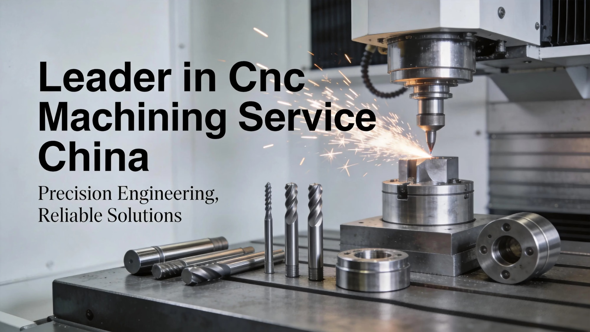
Leader in Cnc Machining Service China
127High-precision CNC machines
16Simultaneous 5-axis centers
±0.005 mmAchievable tolerance
99.99%Qualification rate
Where it goes wrong

Four ways parts fail before they ever ship

Most of these are decided at the drawing stage, not on the machine.

01

Tolerance stack exceeds the process

You call out ±0.01 mm on a 4,000 mm long bracket. Thermal growth alone can move the part more than that between morning and afternoon. The shop either scraps the run or ships it out of spec and argues later. Both cost you weeks.

02

Tool wear shows up as size drift

A 6 mm end mill cutting 4140 loses edge sharpness fast. By part 200 the slot is 0.03 mm wide. If nobody tracks flank wear or adjusts offsets, the last parts in the batch fail incoming inspection and the whole lot gets questioned.

03

Wrong holemaking method for the ratio

Drilling a Ø8 mm hole 120 mm deep with a standard twist drill walks off center. Boring needs a pre-existing hole. Reaming only corrects size and finish. Pick the wrong one and you rework the part or loosen the tolerance.

04

Quote arrives after the design is frozen

You send STEP files on a Friday, get cost back the next week, and find out the thin wall needs a different setup. Changing the model now means a new drawing revision, a new quote, and a slipped build date.

How we help

Resources that answer the question before the chips fly

Reference material for the decisions that set cost, lead time and yield.

CNC Lathe Technical Specifications Terminology
Process selection

Match the method to the feature, not the habit

Holemaking gets argued about more than any other operation. Drilling removes most of the material and sets position. Boring corrects straightness, size and roundness on a hole that already exists. Reaming finishes to size with a controlled surface, but it follows the existing axis and will not fix a hole that is off location. If the depth-to-diameter ratio passes about 5:1, a standard twist drill starts to wander, and you need a pilot, a peck cycle, or a gun drill instead.

Turning and boring are not interchangeable either. Turning works on the outside diameter of a part that spins. Boring works on an internal diameter, and on a mill it usually runs as an interpolated or single-point operation. A turned part with a tight bore often needs both operations on the same machine to hold concentricity, which is why mill-turn centers matter for parts like hydraulic manifolds and sensor housings.

  • 1
    DrillingRoughs and positions. Fast, but the hole will not be round or on size.
  • 2
    BoringCorrects location, roundness and size on an existing hole.
  • 3
    ReamingFinishes to size and surface. Cannot move a hole that is off axis.

Get Instant Quote

cnc machining
Tolerance and wear control

Hold size by watching the tool, not the clock

Precision does not come from a single machine spec. It comes from controlling the variables in order. On our 5-axis centers we hold ±0.005 mm on features that fit that envelope, and ±0.0002 in when a drawing is dimensioned in inches. Aluminium 6061 and 7075 behave differently under the same cutter, and titanium TC4 (Ti-6Al-4V) will work-harden if the feed is too light. The toolpath has to match the alloy, not the other way around.

Tool wear is the quiet variable. Flank wear raises cutting force, which pushes the part and changes the finished size. Crater wear on the rake face weakens the edge and causes chipping. We track wear by part count and by measuring the feature, then adjust offsets before the size drifts past the limit. That is how a 10,000 part run stays inside tolerance instead of drifting out at part 3,000. Surface finish follows the same logic: Ra 0.2–0.8 μm needs a sharp edge and a stable setup, not just a slower feed.

  • 1
    Flank wearSize drift and higher force. Compensate with offsets.
  • 2
    Crater wearEdge chipping. Change the insert before finish passes.
  • 3
    Built-up edgeCommon on aluminium. Raise speed or change coating.

Talk to an Engineer

Selection table

Choosing the holemaking method

Pick by diameter, depth ratio and what the drawing actually controls.

MethodBest forWatch out for
DrillingRoughing, position, L/D under 5:1Wander on deep holes
BoringStraightness, roundness, size correctionNeeds an existing hole
ReamingSize and finish on an on-axis holeWill not correct location
Gun drillingDeep holes, L/D above 10:1Needs high-pressure coolant
Interpolated millingLarge bores, interrupted featuresSlower than a boring bar
What we run

Machining and finishing under one roof

One supplier from prototype to production, with inspection reports on request.

01

5 Axis CNC Machining

16 simultaneous 5-axis centers for contoured surfaces, undercuts and parts that would need four setups on a 3-axis machine. Fewer setups means fewer datum shifts and tighter true position.

02

CNC Milling & Turning

27 three-axis machines, 12 four-axis mills and 16 mill-turn centers. Good fit for prismatic housings, shafts, manifolds and sensor bodies in aluminium, stainless and titanium.

03

Swiss-Type Turning

For long, slender parts where a conventional lathe would deflect. Guide-bushing support keeps diameter and concentricity stable on small-diameter work.

04

Rapid Prototyping

Bridge parts for fit checks and design review before you commit to tooling. Same inspection routine as production, so the data transfers cleanly.

05

Sheet Metal & Die Casting

Enclosures, brackets and frames when a machined part is the wrong answer on cost. We will say so if stamping or casting fits better.

06

Surface Finishing

Anodizing, plating, powder coating, bead blasting and laser marking with a minimum character height of 1.5 mm. Finish specs are checked against the drawing.

Capability range

What the shop can take on

Numbers are the limits of the equipment, not a promise on every feature.

ItemRangeNotes
Maximum part size4,000 mmLargest travel is 4,000 × 400 × 150 mm
Standard tolerance±0.005 mm±0.0002 in on imperial drawings
Fine surface finishRa 0.2–0.8 μmNeeds a dedicated finish pass
As-machined finishRa 1.6–3.2 μmTypical on non-critical faces
Minimum order1 partPrototype to 10,000+ part runs
Quote turnaround12 hoursIncludes free DFM analysis
Why engineers send us the hard parts

Six numbers that decide the job

No slogan. Just the limits and the process behind them.

±0.005 mm

Tolerance on fitted features

Held with in-process measurement and offset adjustment, not by hoping the first part is right. We check raw material, monitor the cut, and inspect before shipment. Reports on request.

16

Simultaneous 5-axis centers

Complex geometry in one setup. Fewer re-fixtures means less error stacked into true position, and shorter cycle time on contoured parts.

4,000 mm

Maximum processing size

Long rails, frames and structural parts that most shops cannot fit. Large travel is 4,000 × 400 × 150 mm, with a Ø400 mm rotary table for angled features.

12 h

Quote and DFM turnaround

You get cost and manufacturability notes together. If a thin wall, deep pocket or tight corner will drive cost, you hear it before you commit.

3–5 days

Typical shipment window

Production can start within 24 hours of a released order. Historical late-delivery probability sits below 2%.

1

Minimum order quantity

One prototype or a 10,000+ part run, quoted the same way. Uploads stay confidential and an NDA is available on request.

15 yearsMachining since 2011
7,600 m²Manufacturing space
150Technicians
3Wholly-owned plants
Sector requirements

What different industries need, and what we deliver

cnc machining

Aerospace brackets

Thin ribs, tight true position, traceable material lots. We machine to the drawing and hold the inspection record.

  • ±0.005 mm
  • 100% inspection
cnc machining

Automotive & EV housings

Repeatable bore and face geometry across a production run, with process monitoring between the first and last part.

  • IATF 16949
  • 10,000+ parts
cnc machining

Medical device bodies

Stainless 316L and titanium parts with clean finishes and documented process control, from prototype through pilot build.

  • ISO 13485
  • Ra 0.8–1.6 μm
cnc machining

Robotics joints and links

Angled faces and bores cut in one 5-axis setup so mating parts line up without hand fitting on the bench.

  • 5-axis
  • One setup
FAQs

Questions engineers ask before sending a drawing

What tolerance can you actually hold, and when should I loosen it?

We hold ±0.005 mm on fitted features when the geometry and material allow it. On long parts, thermal movement and machine geometry start to dominate, so a 4,000 mm rail at ±0.005 mm is a different problem than a 40 mm bore at the same number.

Loosen any tolerance that does not do work. Clearance holes, non-mating faces and cosmetic surfaces rarely need a tight callout, and a loose one removes a finish pass and a setup.

When should I choose boring over reaming?

If the hole must be corrected for location, straightness or roundness, bore it. Reaming only controls size and surface finish, and it follows whatever axis the pre-drilled hole already has.

If the pre-drill is on location and you only need the last few microns plus a better surface, ream it. It is faster than single-point boring on small diameters.

How do you deal with tool wear on a long run?

We track wear by part count and by measuring the feature, then adjust offsets before the size drifts out of tolerance. Flank wear raises cutting force and pushes the finished size; crater wear chips the edge and ruins the finish.

On aluminium, built-up edge is the common failure and it shows up as a torn surface. We change speed or coating rather than slowing the feed.

Can you work from a 2D drawing instead of a 3D model?

Yes. A fully dimensioned drawing with datums and a tolerance block is enough for most turned and milled parts. We will ask about anything ambiguous rather than guess.

If you have a STEP file, send both. The model settles geometry questions and the drawing settles tolerance and finish questions.

What does the free DFM analysis cover?

We look at wall thickness, corner radii, hole depth ratios, datum choices and any feature that needs a special cutter or an extra setup. You get notes with the quote, within 12 hours.

The point is to surface cost drivers before the design is frozen. Changing a corner radius is cheap on screen and expensive after the first run.

Which materials do you machine most, and which cause trouble?

Aluminium 6061-T6, 7075 and 2024 are routine, along with stainless 303, 304, 316L and 17-4PH. Steel 1018, 1045 and 4140 are also common.

Titanium TC4 (Ti-6Al-4V) and Inconel need lower speeds, rigid setups and more attention to heat. They machine fine, but they will not run at aluminium feeds.

How do you handle finishes and their effect on tolerance?

Anodizing and plating add or remove a thin layer, which can move a dimension. If a coated surface is also a fits surface, say so on the drawing and we will plan the pre-finish size.

Laser marking needs a minimum character height of 1.5 mm to stay legible after coating.

What do you need to quote a job?

A 3D model or 2D drawing, the material, the quantity and any finish callout. If you have a target tolerance or a critical feature, flag it.

Uploads stay confidential, an NDA is available on request, and there is no minimum order quantity. One part is fine.

Send the drawing. Get cost and DFM notes in 12 hours.

One prototype or a 10,000+ part run, quoted the same way.

12-hour quote100% inspectionNo MOQNDA on request

Trusted by engineers and manufacturers worldwide

Tesla Ford Motor Company BYD Auto Denso Magna International Boeing Airbus Medtronic KUKA FANUC