GreatLight CNC Machining Factory logo
CNC Machining
Rapid Prototyping
Materials
Industries
News
About GL

Get Instant Quote

Shop-Floor Reference

Machinist Resources for Shop-Floor Decisions

A working reference for engineers and machinists: cutting data, tool choice, GD&T callouts and the checks we run before a part ships. Written from the floor, not from a catalog.

127 CNC machines±0.005 mm16 five-axis centersNo MOQ
CNC Lathe Technical Specifications Terminology
15 yearsMachining since 2011
127High-precision CNC machines
±0.005 mmAchievable tolerance
99.99%Qualification rate
Where it goes wrong

Four Problems That Show Up on the Floor

01

A drawing that cannot be made twice

The part passes on the first run, then fails on the second. Usually the datum is implied rather than stated, or a tight tolerance sits on a surface nobody can hold after heat treat. Fix the drawing before you fix the machine. A drawing that only one machinist can read is a single point of failure, so we mark up the datum scheme during DFM review and send it back with the quote.

02

Speeds and feeds copied from a chart

Surface speed depends on hardness, tool coating, coolant and rigidity. A number that works on a rigid 40-taper mill chatters on a long-reach end mill. The scrapped part at hour five is the real cost, and it never shows up on the quote. We log the productive cutting parameters per material and update them when a tool change moves the number.

03

A finish callout nobody measured

Ra 0.4 μm on a 200 mm bore means a specific stone, a specific feed and a specific inspection method. If the callout says Ra 0.8–1.6 μm but the drawing also demands a mirror look on a sealing face, the two requirements were never reconciled. Ask what the surface actually does before you tighten it.

04

Prototype data that never reaches production

The first article runs on a five-axis center with a skilled setup. Volume runs on a different machine with a different fixture, and dimensions drift. Hand over the setup sheet, the tool list and the inspection report at the same time you hand over the CAD file. Otherwise the second run restarts from zero.

How we work

From Drawing Review to Shipped Part

One route, from the file you send to the box on the dock.

CNC Machining Services Online
DFM and setup

Manufacturability Review Before Metal Moves

Every job starts with a manufacturability review, not with a program. We read the drawing for datum structure, tolerance stack, tool reach and feature accessibility. If a bore needs a 0.8 mm radius cutter at 6× diameter reach, we say so before the quote lands, because that single feature can double cycle time. The review comes back inside 12 hours with the quotation.

After approval we fix the setup: which faces get machined in which order, where the soft jaws or fixture plate locate, and which dimensions must be probed in-process rather than checked at the end. For parts up to 4,000 mm we can hold a single setup across a long bed and avoid the stack-up error that comes from re-clamping.

  • 1
    Datum scheme agreed up frontWe propose the primary, secondary and tertiary datums and confirm them with you.
  • 2
    Tool reach checked against geometryDeep pockets and internal radii get flagged before programming.
  • 3
    Fixture plan includedSoft jaws, vacuum plates or custom fixtures, decided before the first cut.

cnc machining
Process control

Cutting Data, Tool Life and In-Process Checks

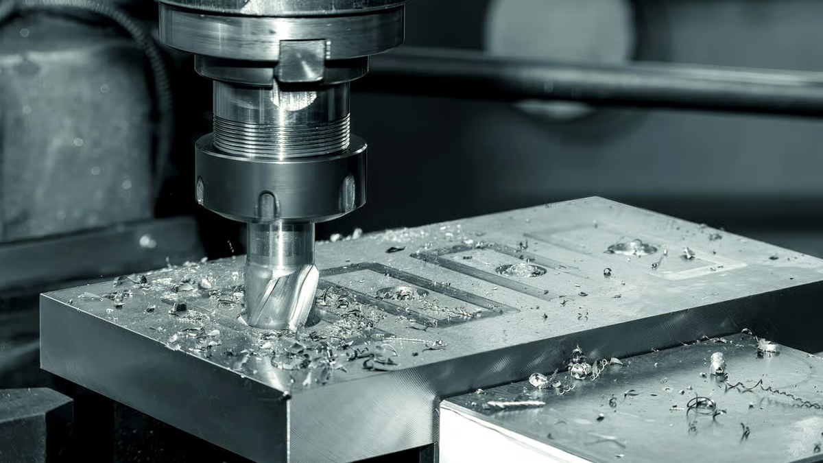
Speeds and feeds are starting points. On the floor we adjust feed per tooth, depth of cut and coolant pressure until the chip breaks cleanly and the tool load sits inside a stable band. Aluminum 6061 and 7075 run at very different surface speeds, and 17-4PH in the H900 condition will work-harden under a rubbing cut, so the pass has to bite.

Inspection is built into the route rather than bolted on at the end. Raw material certificates are checked on receipt, critical dimensions are monitored during the run, and every part gets a final inspection before it is packed. Reports are available on request, including first article inspection for the dimensions you nominate. Where a customer needs it, we hold ±0.005 mm on the features that matter and leave the rest at general tolerance.

  • 1
    Material-specific parametersAluminum, stainless, tool steel, titanium and copper alloys each get their own starting data.
  • 2
    Tool life trackingWe replace inserts on a count, not on a hunch, so the last part matches the first.
  • 3
    Documented inspectionRaw material, in-process and final checks, with reports on request.

Get Instant Quote

Selection guide

Which Process Fits Which Part

Use this to decide where a feature should be cut, and where it should not.

Feature or part typeRecommended routeWhy
Deep pocket, single setup5-axis simultaneousShort tool, less re-clamping, tighter position
Prismatic plate, 2 faces3-axis with soft jawsFastest cycle, lowest setup cost
Round part with cross holesMill-turn centerOne chucking, no second-op runout
Thin washer under 1 mmFine blanking or grindingTurning distorts thin stock
Long shaft over 2,000 mmLong-bed milling or turningAvoids stacking two setups
Hardened tool steelPre-machining plus grindingCuts cost before heat treat
Prototype in 3 days3-axis plus hand finishingNo fixture lead time
What we do

Capabilities Behind the Reference Data

01

5-Axis CNC Machining

16 simultaneous 5-axis centers for contoured surfaces, deep cavities and parts that need five faces in one setup. Impellers, housings and brackets with compound angles.

02

3-Axis and 4-Axis Milling

27 three-axis machines and 12 four-axis mills for prismatic parts, plates, manifolds and fixtures. The workhorse route for volume.

03

CNC Turning and Mill-Turn

16 mill-turn centers with a Ø400 mm rotary table for shafts, bushings and fittings that need cross-drilling or milling in the same chucking.

04

Rapid Prototyping

Machined prototypes and printed parts for fit checks before you commit to tooling. Useful when the geometry is still moving.

05

Surface Finishing

Anodizing, electroless nickel, zinc, powder coat, bead blasting and laser marking with a 1.5 mm minimum character height.

06

Inspection and Reporting

Dimensional reports, material certificates and first article inspection documents supplied with the shipment on request.

Scope

Machine Envelope and Tolerance Band

Numbers we can commit to on a drawing.

ItemRangeNote
Maximum processing size4,000 mmLong-bed milling and turning
Large travel4,000 × 400 × 150 mmSingle setup on long parts
Medium travel750 × 1,150 × 550 mmGeneral prismatic work
Compact travel500 × 500 × 450 mmHigh-speed small parts
Achievable tolerance±0.005 mmOn nominated features
Fine surface finishRa 0.2–0.8 μmGrinding or fine boring
Standard finishRa 0.8–1.6 μmMilling and turning
As-machined finishRa 1.6–3.2 μmNon-critical surfaces
Why GreatLight

What the Numbers Say

15Y

Machining since 2011

Fifteen years of production work across aerospace, automotive, medical and industrial machinery. The process library comes from parts that shipped, not from a textbook.

±0.005

Hold the tight callout

We quote the tolerance the drawing needs. If a feature cannot hold ±0.005 mm on the chosen process, we say so at DFM stage rather than at first article.

12H

Quote and DFM in half a day

Send a STEP file and a 2D drawing. A quotation with manufacturability notes comes back within 12 hours, and production can start within 24 hours of approval.

127

Machines, not a broker network

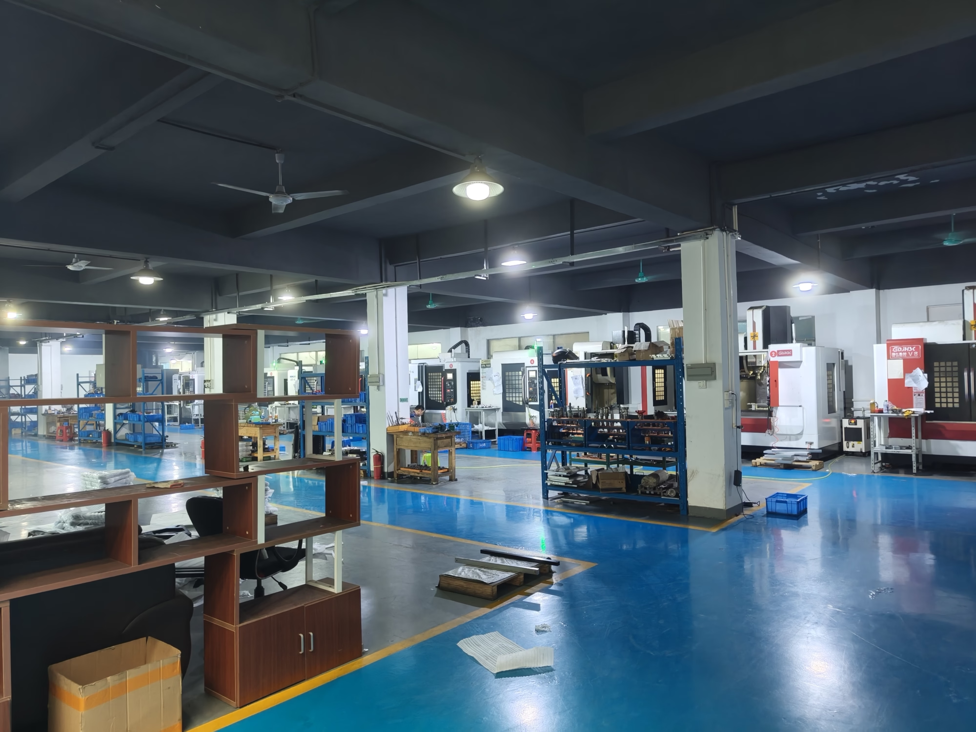
Sixteen 5-axis centers, sixteen mill-turn centers and a full 3-axis and 4-axis floor. Work does not get subcontracted out and re-quoted.

99.99%

Qualification rate

Raw material check, in-process monitoring and final inspection on every part. Reports on request, including first article inspection.

2%

Historical late-delivery risk below 2%

Parts ship in 3–5 days on standard work. Scheduling is done against machine capacity, so the date we give is a date we can hold.

7,600 m²Manufacturing space
150Technicians on staff
3Wholly-owned plants
ISO 9001and IATF 16949 certified
Industry fit

Where These Resources Get Used

Leader in Cnc Machining Service China

Aerospace Brackets

Thin-wall ribs and compound-angle faces cut in one 5-axis setup to avoid re-clamp error.

  • ±0.005 mm
  • 5-axis single setup
  • Ra 0.8–1.6 μm
oplus_262178

Automotive and EV Housings

Aluminum housings with sealing faces and dowel-pin bores, machined on mill-turn centers to keep bore-to-face position.

  • IATF 16949
  • 6061-T6
  • 100% inspection
6011

Medical Instrument Parts

Stainless 316L and 17-4PH components with fine bores, deburred and passivated before packing.

  • ISO 13485
  • Ra 0.2–0.8 μm
  • 17-4PH
GreatLight Metal new factory building

Industrial Machinery Frames

Long plates and frames up to 4,000 mm machined on a long bed so one datum carries across the whole part.

  • 4,000 mm
  • ±0.005 mm
  • No MOQ
FAQs

Questions Machinists and Engineers Ask

What surface speed should I start with on 6061 aluminum?

Treat it as a starting point, not a rule. On 6061-T6 with a coated carbide end mill and flood coolant, most shops run high surface speed and a feed per tooth that keeps the chip thick enough to carry heat away. If the chip turns to powder, the feed is too light and the tool will rub.

The limiting factor is usually the machine, not the material. A small spindle at high rpm may not have the torque to keep the feed up, so you back off speed and hold the chip load instead. Check the tool load meter before you trust the chart.

When does 5-axis actually save money?

It saves money when the alternative is three or four setups with a fixture between each one. Every re-clamp adds position error and setup hours. If a part has features on four or five faces, or a contoured surface that would need a ball-nose sweep with a long tool, 5-axis usually wins on total cost even at a higher hourly rate.

It does not save money on a simple prismatic plate. A 3-axis machine with soft jaws will beat it on cycle time and programming effort every time.

Why does my stainless part work-harden during tapping?

The tap rubs instead of cutting. On 304 and 316 the material hardens at the surface when the tool slides, and the next revolution cuts into harder metal. Small taps break quickly.

Use a cut tap with the correct drill diameter, keep the feed rigid, and use a tapping fluid rather than a general coolant. On 17-4PH in the H900 condition, pre-drill slightly oversize within thread tolerance and keep the tap moving forward without dwell.

How do I call out a finish that someone can actually measure?

Name the surface function first, then the Ra value. A sealing face, a bearing bore and a painted cover need very different finishes. If the drawing says Ra 0.4 μm but the part is a non-contact cover, you are paying for grinding you do not need.

Also state the inspection method. Ra measured on a curved surface with a skidless pickup reads differently from a flat comparator. When in doubt, specify Ra 1.6–3.2 μm as-machined and tighten only the faces that seal, slide or mate.

What is a reasonable tolerance to put on a general drawing?

Put the general tolerance block at a level the process holds without effort, then tighten individual features. On a milled aluminum part, general tolerance at ±0.1 mm is routine. Holding ±0.005 mm on every dimension multiplies cost and inspection time for no functional gain.

Pick the two or three features that control fit and position, and mark those. Everything else can stay loose. That one habit removes most of the arguments at first article.

Do I need a 2D drawing if I send a STEP file?

Yes, for anything with a tight tolerance or a finish callout. A STEP file carries geometry but no tolerance, no datum and no surface requirement. The machinist has to guess, and guesses get quoted as assumptions.

Send the 3D model for shape and the 2D drawing for the tolerances, datums and notes. If you have no drawing yet, send a marked-up model screenshot with the critical dimensions and we will work from that and confirm in the DFM notes.

How do I keep a prototype design from breaking in production?

Record how the prototype was made. Which machine, which fixture, which tool, which inspection points. When the design moves to a different process, those notes are the baseline for comparison.

Then set the critical dimensions before the second run starts. If the first article drifts outside the band, you know it at hour one instead of at the end of the batch.

What do you need to quote a part in 12 hours?

A 3D file in STEP or IGES, a 2D drawing with tolerances and finish callouts, the material and the quantity. Tell us which features are critical, and whether the part is a prototype or a production run.

If a drawing does not exist yet, send the model plus a note on function. We can still quote and add manufacturability notes. Uploads stay confidential, and an NDA is available on request.

Send a Drawing, Get a Quote and DFM Notes

Upload a STEP file and a 2D drawing. A quotation with manufacturability feedback comes back within 12 hours.

12-hour quote100% inspectionNo minimum order quantityNDA on request

Trusted by engineers and manufacturers worldwide

Tesla Ford Motor Company BYD Auto Denso Magna International Boeing Airbus Medtronic KUKA FANUC