
01
Tolerance stack nobody checked
A bore is called at ±0.01 mm, the mating pin at ±0.01 mm, and the assembly only has ±0.02 mm to give. The parts pass incoming inspection and still will not go together. We ask for the mating callout before quoting.
Reference material written for the shop floor: tolerance charts, G-code and M-code notes, deburring and finishing guides, plus the 5-axis capacity behind them. Use it to check a design before you cut metal.

Most rejects start at the drawing, not the spindle.
A bore is called at ±0.01 mm, the mating pin at ±0.01 mm, and the assembly only has ±0.02 mm to give. The parts pass incoming inspection and still will not go together. We ask for the mating callout before quoting.
A 0.2 mm rollover on a cross-hole edge jams an automated feeder. Deburring is not a line item on the drawing, so it gets skipped. Add an edge condition note and the cost becomes visible early.
Ra 0.8 μm on a 4,000 mm face and Ra 0.8 μm on a Ø12 mm bore are two different operations. Calling both the same way adds polishing time you did not budget for.
A 3-axis setup that worked for five pieces can double cycle time at 10,000. The fixture, not the machine, becomes the bottleneck.
Two things decide whether a part comes out right: the numbers on the drawing and the setup that holds it.
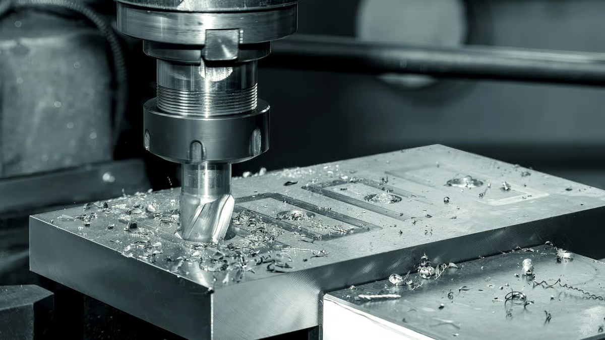
A general tolerance block of ±0.1 mm covers most features on a machined part. Tightening everything to ±0.005 mm adds inspection time and scrap risk without improving function. We mark the two or three features that actually locate the part and leave the rest loose.
On a 4,000 mm part, thermal drift and workholding deflection matter more than spindle accuracy. For long parts we plan roughing and finishing in separate setups so the material settles before the final pass.
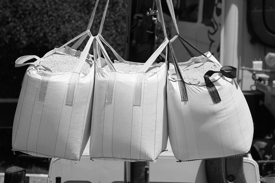
G-code tells the machine where to move. M-code tells it what to switch on: spindle, coolant, tool change, pallet. When a part comes out short on one side, the cause is usually a work offset or a tool length that was set against the wrong face.
For five-sided parts we post from the CAM model and verify the rotary table position offline. A Ø400 mm rotary table gives enough swing for most housings, and the 16 simultaneous 5-axis centers handle undercuts that would need three setups on a 3-axis machine.
Start from the geometry and the quantity.
| Feature | Process | Step-over / feed | Watch for |
|---|---|---|---|
| Deep pocket, L/D over 4 | 3-axis with long reach | Light radial, 0.1 × D | Tool deflection and chatter |
| Five-sided housing | 5-axis simultaneous | 0.3 × D radial | Rotary table clearance |
| Ø6 mm or smaller bore | Micro machining | 0.05 mm step-over | Heat build-up in the tool |
| Long shaft, Ø25 mm | Swiss / mill-turn | Bar feed, steady rest | Bar whip above 3,000 rpm |
| Thin wall under 1 mm | 4-axis with support | Finishing pass 0.2 mm | Spring-back after clamping |
One shop for the prototype and the production run.
16 simultaneous 5-axis centers for undercuts, angled faces and housings that would need multiple fixtures on a 3-axis machine. One setup means one datum, which is where accuracy usually comes from.
27 three-axis machines and 12 four-axis mills handle plates, brackets and prismatic parts. Good choice when the geometry is open and the volume is high.
16 mill-turn centers cut shafts, fittings and threaded parts in one cycle. Less handling means fewer re-datum errors between the milled flats and the turned diameter.
From a single piece to a 10,000+ run with no minimum order quantity. Useful when you need to test fit before committing to hard tooling.
Bent and formed enclosures, brackets and panels. We keep the flat pattern and the formed part under one drawing revision.
Anodizing, plating, powder coating, bead blasting and polishing. Laser marking down to 1.5 mm character height for traceability.
Match the part to the travel before you send the file.
| Machine group | Travel | Typical parts |
|---|---|---|
| Large gantry | 4,000 × 400 × 150 mm | Long beams, rails, tooling plates |
| Medium 5-axis | 750 × 1,150 × 550 mm | Housings, manifolds, brackets |
| Medium 5-axis | 600 × 600 × 600 mm | Enclosures, covers, plates |
| Compact 4-axis | 500 × 500 × 450 mm | Fittings, connectors, small bodies |
| Mill-turn | Ø400 mm rotary table | Shafts, bushings, threaded parts |
Every figure below is a shop specification, not marketing copy.
Three wholly-owned plants and 7,600 m² of manufacturing space in Dongguan, plus a factory in Singapore at No.3 Joo Koon Circle.
16 simultaneous 5-axis centers, 12 four-axis mills, 27 three-axis machines and 16 mill-turn centers, run by 150 technicians.
Equivalent to ±0.0002 in. Held on located features with the right workholding, not on every face of the part.
Ra 0.2–0.8 μm when the drawing calls for it. As-machined parts sit at Ra 1.6–3.2 μm.
Quotation plus free DFM analysis within 12 hours. Production can start within 24 hours of approval.
From one prototype to 10,000+ part runs. Uploads stay confidential and an NDA is available on request.
Traceable material and documented inspection for structural parts.

Process control that holds across a production run, not just the first article.

Clean deburring, controlled finish and material certificates on file.
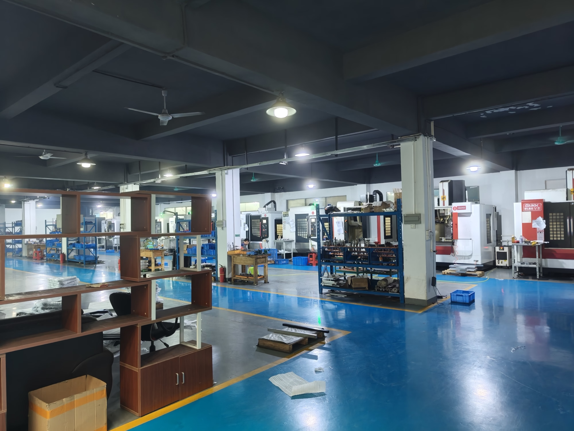
Repeatable datums so the second unit bolts into the same fixture.
Start with ±0.1 mm for non-critical features and tighten only where the part locates or seals. A drawing with two tight features is cheaper to make and easier to inspect than one with twenty.
We can hold ±0.005 mm on located features. If you are unsure which ones matter, send the mating part and we will mark them in the DFM report.
If every feature can be reached from one direction, 3-axis is enough and usually faster per part. Angled holes, undercuts and five-sided housings push you toward 5-axis because they avoid a second or third setup.
Each extra setup adds a datum shift. On parts with tight position tolerance between faces, fewer setups matter more than spindle speed.
Cross-drilled holes, threaded entries and milled edges that touch a mating surface all need an edge condition. If the drawing says nothing, the machinist decides, and that decision changes from operator to operator.
Write the edge callout as a note, for example 0.1 mm max edge break. Then deburring becomes a measurable step instead of a surprise at assembly.
As-machined surfaces land around Ra 1.6–3.2 μm. That is fine for brackets, covers and most non-sealing faces.
For Ra 0.2–0.8 μm we add a finishing pass with a smaller step-over, and sometimes bead blasting or polishing. It costs time, so call it out only where a seal, a bearing or a sliding fit needs it.
Read the block sequence first, not the individual words. G00 and G01 set the motion mode, G41 and G42 bring cutter compensation in and out, and M08 controls coolant. An M00 in the middle of a cycle usually means the programmer wants a measurement.
If a feature is consistently off, check the work offset and tool length before editing the program. The code is rarely wrong on a proven post.
Confirm units, datum scheme and thread callouts. Mixed metric and inch dimensions on one drawing cause more scrap than any machining error.
Include the mating part or the assembly fit where it exists. It tells us which tolerances are functional and which are decoration.
Yes. There is no minimum order quantity, so one prototype and a 10,000+ run go through the same shop. The setup changes between them, and we say so in the quote.
For production we usually add a fixture that the prototype did not need. That is where cycle time and repeatability come from.
Quotation and free DFM analysis come back within 12 hours. Production can start within 24 hours of approval, and parts ship in 3–5 days.
Every part is inspected before shipment: raw material check, in-process monitoring and final inspection. Reports are available on request.
Upload your file and we will return a quotation with free DFM analysis within 12 hours. No minimum order quantity, from one part upward.
12-hour quote100% inspectionNo MOQNDA on request
Trusted by engineers and manufacturers worldwide










Upload your 3D model or 2D drawing and get a quotation with a free DFM analysis. Maximum processing size 4,000 mm.
CNC Metals 13 grades
CNC Plastics 10 grades
Machines & processes 12 options
Surface & post-processing 10 options
Material: not selected Machine: not selected Post-process: not selected
Fill in this short form and we'll open WhatsApp with your message ready to send. We only use these details to reply to you.
Nothing is sent until you press send inside WhatsApp.