
5 DMLS 3D Printing Tips to Cut Costs Now
Most of the cost in a metal build sits in supports, laser time, post-processing and rework, not in the powder. This page walks through five decisions that move those numbers, written for design engineers and buyers who already run DMLS or are quoting it. You should be able to tell which parts suit the process and which should be machined instead.
Where DMLS Cost Actually Accumulates
Ask for a cost breakdown on a metal build and the powder line is usually smaller than people expect. The money goes to machine hours, support structures, depowdering and support removal, then to whatever the part still needs after it leaves the machine: face milling, thread cutting, bore reaming, heat treat, inspection. If a feature is machined later anyway, printing it at high resolution is wasted laser time.
That is the lens for everything below. Every tip either removes laser time, removes manual labor, or removes a second operation. Nothing here is about buying powder cheaper.
A good habit before quoting: mark each surface on the drawing as as-built, machined, or cosmetic. Surfaces marked as-built need the tight layer thickness and clean orientation. Everything else can tolerate rougher layers and stock left for a cutter.
Design Self-Supporting Geometry Instead of Paying for Supports
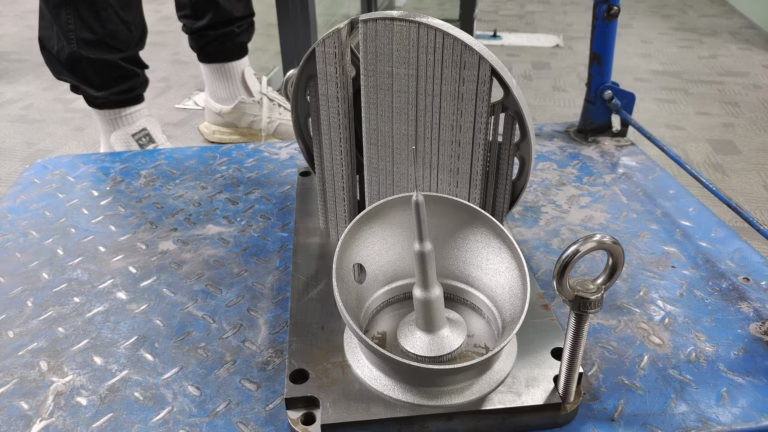
Supports are melted powder holding up overhangs. They consume material, laser time and a lot of bench time, because someone has to cut them off, grind the witness marks and often blend the surface. On parts with heavy overhangs, that block of work can dominate the quote.
The fix is orientation and chamfering, not support reduction software. Rotate the part so the largest flat face sits on the plate. Replace a horizontal overhang with a 45° or gentler slope. Add a chamfer at the bottom edge of a bore or pocket so the first layers have something to sit on. A single 0.5 mm chamfer can remove a column of supports under a blind bore.
Some geometry has to be supported, and that is fine. Internal channels, lattice regions and long horizontal bridges still need anchoring, because sagging metal cannot be reworked. The judgment call is whether the support cost is smaller than the redesign cost. For a one-off manifold, reorienting is almost always cheaper. For a part with functional internal channels that must stay round, supports and careful removal are the safer route.
Keep the build direction in mind during concept design. Draft angles of 5–10° on vertical walls do not change the part's function but do change how the laser lays down each layer. Flat top faces come out cleaner than sloped ones, so where a surface finish matters, orient it upward or downward relative to the build.
- 1Reorient firstRotate to put large faces on the plate before adding supports.
- 2Chamfer bottom edgesA 0.5 mm chamfer under a bore can delete support columns.
- 3Keep supports where sag mattersInternal channels and bridges still need anchoring.
Set Layer Thickness by Zone, Not for the Whole Part
A uniform 30 μm build gives a good as-built surface and a long build time. A uniform 60 μm build is faster but leaves visible stair-stepping on curved surfaces. Neither is the right answer for a part that has both a sealing face and a hidden internal boss.
Split the part into zones. Keep the fine layer thickness on surfaces that stay as-built and carry function: sealing faces, flow surfaces, visible exterior. Use coarser layers on hidden geometry, internal bosses, and any face that will be machined after printing. On a part with a lot of hidden volume, this is one of the larger savings available because laser time scales with the number of layers.
The same logic applies to stock allowance. If a threaded hole or a bearing bore will be cut with an end mill, do not print it to near-net size. Leave 0.3–0.5 mm of stock and let the cutter establish the dimension. Printed threads rarely hold the tolerance class an engineer expects, and chasing them with a tap after a rough printed profile is slower than cutting from stock.
One caution: zone changes create a transition in the melt pool and can leave a faint band on the surface. Put the transition on a non-critical face or under a machined allowance.
Layer Thickness and Post-Process by Surface Type
Use this as a starting point when marking up a drawing. Final values depend on geometry and material.
| Surface type | Layer thickness | Post-process | Why |
|---|---|---|---|
| Sealing or mating face | 30 μm | Fine face milling | Flatness and Ra 0.8–1.6 μm |
| Bearing bore | 30 μm plus stock | Boring or reaming | Roundness and fit class |
| Threaded hole | Coarse plus stock | Thread mill or tap | Printed threads rarely hold class |
| Internal cooling channel | 30–40 μm | Flow check only | Roundness affects flow |
| Hidden boss or rib | 60 μm | None | Never seen, never touched |
| Cosmetic exterior | 30 μm | Bead blast or polish | Stair-stepping is visible |
| Datums and mounting pads | Coarse plus stock | CNC skim cut | ±0.005 mm needs a cutter |
Nest and Batch to Fill the Build Plate
DMLS is a batch process. The laser does not care whether it is scanning one part or thirty; it cares about total melt area and layer count. A plate that runs half empty still costs the same machine hours and the same gas, so the cost per part is roughly doubled by poor nesting.
Part height drives build time more than part count. Two short parts stacked in the same job add less time than one tall part. If your design has a tall, thin section, ask whether it can be split into two shorter printed pieces joined by a machined feature or a welded joint. Height reduction is often the single biggest lever on laser time.
Sharing supports across nested parts is standard practice and worth asking about. When two parts sit close together, a common support wall can serve both, which cuts material and removal labor.
The practical limit is not plate area but scheduling. Mixing materials in one build is not an option, and mixing a 30 μm zone part with a 60 μm zone part forces the whole job to the finer setting. Group parts by material and by layer requirement, then fill the remaining area with parts that share those settings.
Hybridize: Print the Shape, Machine the Critical Features
DMLS is good at internal channels, organic ribs, conformal cooling and consolidated assemblies. It is not good at tight tolerances on flat faces, bores and threads. Trying to make the printer do both raises cost and risk at the same time.
The hybrid route prints near-net with stock on critical features, then finishes them on a CNC. On a 5-axis machine, one setup can face a mounting pad, bore two bearing seats and cut threads without moving the part between operations. Fewer setups means less stack-up error, which is how the ±0.005 mm tolerance gets held on features that sit on printed material.
This split also changes the design rules. Once a face is going to be machined, it no longer needs a fine layer, a specific orientation, or a support-free build direction. You can orient the part purely to reduce supports and build height, then let the cutter take care of the rest.
There is a limit. If more than about half the part volume ends up as machining stock, the printed blank is probably the wrong process, and a billet or a casting will be cheaper. The break-even is geometry dependent, so it is worth asking for both routes on the same drawing.
- 1Print near-netStock on bores, faces and threads; fine layers only where as-built.
- 2Finish in one setup5-axis machining keeps datums without re-fixturing.
- 3Check the ratioIf most of the volume becomes chips, switch to billet or casting.
Vet the Supplier on Process Integration, Not on Price per Gram
A print bureau that only prints will quote you a printed part and hand back the finishing problem. Support removal, heat treat, machining, inspection and documentation then get sourced separately, and each handoff adds cost, lead time and somebody to blame when a dimension drifts.
Ask what the supplier does in-house. If the answer includes machining, surface finishing and inspection under one quality system, the printed blank and the finished part share one traceability chain. That matters most for regulated work in medical, automotive and aerospace, where the certificate has to cover the whole route.
Ask for the material certificate and the inspection report before the first article, not after. For titanium and Inconel, powder chemistry and reuse policy affect mechanical properties, so a supplier should be able to say how many times powder has been recycled and how they track it.
Finally, ask for a DFM review at quote stage. A supplier who flags a support-heavy orientation or a thread that should be machined is saving money before the first layer is scanned. If the quote comes back with no comments on the drawing, that is a signal in itself.
DMLS Cost Questions Engineers Ask
Is 60 μm always cheaper than 30 μm?
Only on surfaces that stay as-built and hidden. The coarser layer cuts build time, but if the surface is later machined, the saving is real and the roughness does not matter.
If the surface is functional and stays as-printed, the coarser layer usually costs more overall because the finish has to be corrected by hand or by an extra operation.
How much stock should I leave for post-machining?
For bores and faces finished on a CNC, 0.3–0.5 mm per side is a workable range on most titanium and stainless builds. It is enough to clean up distortion and layer steps without adding much laser time.
Threads should be left undersized and cut to size. Do not print a thread and expect it to hold a fit class.
When is DMLS the wrong process?
When the part is a simple prismatic block with no internal channels and no consolidation benefit. A billet on a 3-axis or 5-axis machine will be faster and cheaper.
It is also the wrong process when the only reason to print is a tight tolerance on a flat face or a bore. Those features come off a cutter anyway.
Can supports be avoided completely?
On some geometries, yes. Self-supporting angles, chamfered overhangs and a good build orientation can remove most supports.
Internal channels and long horizontal bridges still need anchoring. Removing those supports in software does not remove the sag, it just moves the defect downstream.
What should be in the quote package for a fair comparison?
The 3D model, a drawing with tolerances and surface finish per feature, material and heat treat specification, and the annual volume or prototype quantity.
Mark which surfaces stay as-built. Suppliers who know that can set layer zones and nesting properly instead of quoting the whole part at the finest setting.
How does batch size affect the price per part?
Build height and total melt area set machine time. Filling an empty plate area with parts that share material and layer settings spreads that time across more pieces.
Grouping parts by material and layer requirement is what makes nesting work. Mixed jobs force the whole build to the finest setting.
Send a Drawing, Get a DFM Review and Quote
Upload your model and drawing. We review build orientation, supports, layer zones and which features should be machined, and reply with a quotation and free DFM analysis within 12 hours.
12-hour quote and DFMNo minimum order quantity100% inspection before shipmentNDA on request









