
7 Essential CNC Turning Tips to Boost Precision and Slash Production Costs
A shop-floor guide for engineers and buyers running turned parts on lathes and mill-turn centers. Each tip names the parameter range, the failure it prevents, and when it is not worth the money.
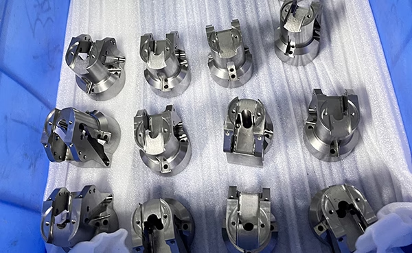
Seven CNC turning tips, in one screen
Toolpath strategy and insert choice set the ceiling
Turning precision is decided long before the insert touches the bar. A CAM toolpath that enters on a straight lead, keeps constant chip load and avoids full-width radial cuts will hold size better than a fast cycle that hammers the insert. On a Ø25 mm 4140 shaft we keep radial depth of cut at 1.5–2.5 mm for roughing at 180–220 m/min, then leave 0.3–0.5 mm for the finishing pass. That finishing allowance is what lets you hold ±0.005 mm without chasing the offset every ten parts.
Offline simulation is the cheapest insurance in the shop. Run stock removal, check for gouges and check that the tailstock and turret do not collide on long parts. For a Ø400 mm rotary table setup, a two-minute simulation beats a crashed tool holder. Skip this step and the first sign of trouble is often a scrapped first article, not a warning on screen.
Insert selection follows the material, not the price list. Aluminum 6061 and 7075 run best on uncoated or polished grades with a sharp edge and high rake; 316L and 17-4PH need a tougher coated grade and a stronger edge hone. Inconel and titanium sit at the far end, where low surface speed and a rigid setup matter more than any single grade.
One detail engineers often miss: the tool holder, not the insert, causes most chatter on slender parts. A Ø12 mm boring bar hanging 60 mm out of the holder will sing even with a perfect insert. Reduce overhang to 4× the bar diameter or less, or add a damping holder. It costs less than the scrap you will make.
- 1Roughing allowanceLeave 0.3–0.5 mm radial stock for the finishing pass on tight-tolerance diameters.
- 2Chip load per revolutionKeep it constant through the cut; sudden jumps in feed mark the surface.
- 3Bar overhangHold boring bar overhang at 4× diameter or less to kill chatter.
In-process inspection and chip control on the floor
Post-process sampling finds a problem after fifty parts are already made. In-process measurement finds it after five. On a bearing seat with a ±0.005 mm band, touch off the feature every 10 to 20 parts with a probe or a shop micrometer and log the reading. If the trend moves 0.003 mm in one direction, correct the offset before it leaves the band. That single habit protects first-pass yield on long runs.
Coolant is a chip-removal system, not a washing system. For 316L and other stringy materials, aim high-pressure delivery at the cutting edge, around 70–100 bar on a dedicated system, so the chip lifts off the rake face instead of welding to it. Flood coolant at 5–10 bar rarely reaches the edge on deep bores, and the chip recuts, which is where poor finish and short tool life come from.
Chip breaker geometry does half the work. A chip that breaks into 20–40 mm C-shapes flows out of the way; a long ribbon wraps the part and stops the cycle. Adjust feed first, then depth of cut, then coolant pressure. Changing all three at once makes it impossible to know what fixed it.
On heat-sensitive alloys, watch the part temperature as much as the chip. Titanium and magnesium transfer heat into the workpiece, so a hot part measures small and cools oversize. Let the part settle to room temperature before the final gauge check, or you will chase a ghost.
- 1Probe intervalCheck critical diameters every 10–20 parts and log the trend, not just the value.
- 2High-pressure coolant70–100 bar directed at the edge works better than flood on deep bores and stringy chips.
- 3Change one variableAdjust feed, then depth of cut, then pressure so you know what actually worked.
Setup time, mill-turn, and DFM input
Setup is where most of the money hides on small lots. Every extra chuck jaw change, every re-zero and every second op adds hours. A mill-turn center that finishes a cross-hole, a flat and a slot in the same grip removes a whole second operation and the concentricity error that comes with it. On a Ø400 mm rotary table job, one setup can replace a fixture and two handoffs.
Multi-axis does not fix a bad drawing. If the part has a deep internal groove, a 0.5 mm corner radius or a tolerance on a non-functional face, the cost is in the geometry. Ask for DFM feedback on the print before quoting. Moving a datum, opening a radius from 0.3 mm to 1.0 mm, or releasing a tight tolerance that does not matter often cuts cycle time without changing function.
Feed and speed should follow the setup, not a generic chart. A rigid, short-overhang setup in 6061 can run 250–350 m/min with a 0.15–0.25 mm/rev feed. The same insert in a slender 17-4PH part may need to drop to 120–160 m/min. Start conservative on a new job, then push once the first ten parts hold size.
Keep a short run log per part number: material, insert grade, speeds, feeds, coolant pressure, measured result. The next order starts where the last one finished instead of from scratch.
- 1One setup, more featuresMill-turn removes second-op concentricity error and a whole handling step.
- 2DFM before quoteDatum, radius and non-critical tolerance changes cut cycle time with no loss of function.
- 3Run logRecord insert, speeds, feeds and measured result so repeat orders start ahead.
Step by step: from print to stable run
Work through these in order. Skipping step 2 or 5 is what causes most of the rework we see.
- 1Review the print for turning-specific riskMark every diameter with a tolerance tighter than ±0.02 mm, every internal groove and every corner radius under 0.8 mm. Those three features drive most of the cost.
- 2Fix datum and tolerance calls with DFMAsk the shop which features can be loosened without changing function. Opening a radius from 0.3 mm to 1.0 mm or dropping a tight call on a non-functional face removes a finishing pass.
- 3Choose the bar, holder and insert togetherMatch insert grade to material: polished sharp edge for 6061/7075, coated tough grade for 316L and 17-4PH, low-speed grade for Inconel and TC4. Keep boring bar overhang at 4× diameter or less.
- 4Simulate and prove out offlineRun stock removal and collision checks in CAM. Confirm the finishing allowance, 0.3–0.5 mm on tight diameters, survives the roughing strategy.
- 5Set cutting data conservatively, then pushStart 6061 at 200 m/min and 0.15 mm/rev, 316L at 120–160 m/min. Raise speed in 10% steps while the surface and the chip stay stable.
- 6Tune the chip before adding pressureAdjust feed first, then depth of cut, then coolant. Aim for 20–40 mm broken chips; use 70–100 bar coolant on deep bores and stringy stainless.
- 7Measure in process on critical featuresProbe or gauge bearing seats and seal grooves every 10–20 parts. Correct the offset when the trend moves 0.003 mm, not when it fails.
- 8Freeze the parameters and log the runWrite insert, speeds, feeds, coolant pressure and measured result into the job record. Lock the offsets before the run continues.
Which tip matters most for your part
Pick the row that matches your part. The right column tells you where the money goes.
| Part situation | First priority | Parameter to watch | When it is not worth it |
|---|---|---|---|
| Long slender shaft, Ø12 mm | Rigid setup and support | Overhang, feed per rev | Short stubby parts do not need a steady rest |
| Bearing seat ±0.005 mm | In-process gauging | Offset drift over the run | Loose fits do not justify probe time |
| 316L high-volume bushings | Chip control and coolant | 70–100 bar at the edge | One-off jobs can run flood coolant |
| 6061 housing, 10,000 pcs | Cycle time per part | 250–350 m/min finishing | Prototype lots gain little from speed tuning |
| Inconel or TC4 ring | Low speed and rigidity | 120 m/min, depth of cut | Aluminum-grade inserts will fail here |
| Part with a deep internal groove | DFM change to the groove | Groove width and radius | If the groove is a seal seat, keep the call |
| Multi-feature, one handoff | Mill-turn single setup | Concentricity across features | Simple turned parts do not need 5-axis |
Fix the design and setup first, then chase speed
Most turned-part cost sits in tolerance calls, setup count and chip control, not in the cutting speed on the last pass. Get those three right and the cycle time usually follows.
Questions engineers ask before a turning run
What tolerance can CNC turning actually hold in production?
On a rigid lathe with a stable material and in-process checks, ±0.005 mm (±0.0002 in) is repeatable on diameters up to roughly Ø100 mm. Beyond that, thermal growth and bar deflection start to eat the band.
If the print asks for tighter than ±0.005 mm, treat it as a grinding or fine-boring feature and say so at quote stage rather than at first article.
When should we use a mill-turn center instead of a lathe plus a mill?
Use mill-turn when the part has cross-features that must be concentric with a turned diameter, or when a second op would need a fixture and a re-zero. One grip removes the stack-up error and the handling time.
If the part is a simple shaft with one flat, a lathe with a live tool is cheaper. Mill-turn earns its place on multi-feature parts and small lots.
How do we stop chips from wrapping the part in 316L?
Break the chip with feed and geometry before adding pressure. Increase feed per revolution in small steps and check the chip shape; the target is 20–40 mm C-shapes, not ribbons.
Then add high-pressure coolant, around 70–100 bar, aimed at the cutting edge. Flood coolant alone often cannot reach the edge on deep bores.
Does a tighter surface finish call always cost more?
Not always. Ra 0.8–1.6 μm is a normal turning result with a sharp insert and a stable setup. Going below Ra 0.8 μm usually needs a wiper insert, a slower finishing pass, or a secondary operation.
Ask whether the finish call is functional. A sealing face needs it. A clearance diameter rarely does, and loosening it can remove a whole pass.
What information should we send with an RFQ for turned parts?
Send the 3D model and the 2D print with tolerances, material and finish, plus the annual quantity and any critical function, such as a bearing seat or a seal groove. Note any feature that cannot be changed.
Quantity matters as much as geometry. A design that is fine at 50 pieces may need a process change at 10,000, and the reverse is also true.
How early should DFM feedback come in?
Before the design is frozen. Datum choice, corner radii and which tolerances are functional are all cheaper to change on screen than on a machine.
A useful DFM review flags the three or four features that drive cycle time and says what each one costs. That is more useful than a generic list of rules.
Send us the turning print and we will review it
Quotation and free DFM analysis within 12 hours. No minimum order quantity, from one prototype to 10,000+ part runs.
12-hour quote±0.005 mm turning100% inspectionNo MOQ
More turning and machining notes
We publish setup notes, tooling trials and inspection data from the factory floor.











