
Laser and CNC: 7 Essential Tips to Slash Production Costs and Boost Accuracy
A practical guide for engineers and buyers who route sheet metal, brackets, housings and machined parts through two processes. It covers where the laser stops, where the CNC starts, and which decisions actually move cost and tolerance. Read it before you release the next drawing.
In this article
- 1
- 2
- 3
- 4
- 5
- 6
- 7
- 8
Key takeaways
Define the Process Boundary Between Laser and CNC
Most cost overruns start with picking a process by habit. A flat bracket with slots and an outer profile that fits inside a 4,000 mm envelope is laser work: fast, no tool wear, minimal heat input on thin sheet. The moment the drawing asks for a counterbore, a thread, a pocket with a floor radius, or a 3D contour, the laser cannot finish the job. That feature goes to a mill.
The useful rule is geometric. If a feature can be described by a 2D profile extruded through the material, the laser does it cheapest. If the feature needs a depth, an internal corner radius, or an undercut, it is a machining feature. Draw the split line on the part before quoting, not after the first article fails.
Watch the material thickness too. Laser cutting holds a tight kerf on thin sheet, but as thickness climbs the cut edge tapers and the heat-affected zone widens. On a 6 mm stainless plate the edge may need a light mill pass anyway, so plan that pass into the routing from the start.
One more boundary: cosmetic faces. The laser leaves a slightly oxidized edge that shows through clear anodize more than through a bead-blasted surface. If the edge is visible on the finished product, either move it to the mill or specify the finish that hides it.
- 1Laser2D profiles, slots, thin walls, sheet up to the machine envelope.
- 2MillPockets, bores, threads, 3D contours, any depth-controlled feature.
- 3SharedFiducials and datum holes cut on the laser, referenced by the mill.
Cut Setups With 5-Axis, Not With More Fixtures
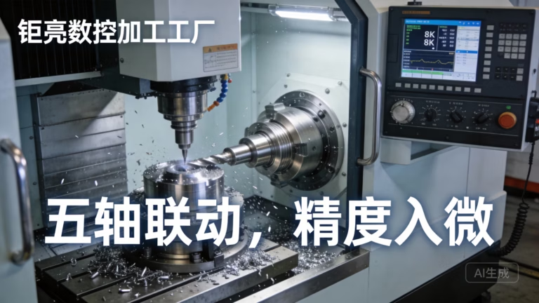
Reclamping is the quiet cost driver. Each new fixture introduces a locating error, and those errors stack. A part that needs three setups on a 3-axis mill can often be finished in one on a 5-axis center with a Ø400 mm rotary table, because the tool reaches nearly every face without the operator touching the vise.
For parts with angled ports, compound faces, or features on five sides, simultaneous 5-axis motion also lets you use shorter tools. Short tools deflect less, so surface finish stays in the Ra 0.8–1.6 μm range without a second finishing operation on a separate machine.
The trade-off is programming time. A five-axis toolpath takes longer to prove out than a three-axis one, and it only pays back on parts with real multi-face geometry. Simple prismatic parts with one machined face should stay on a 3-axis machine. Forcing them onto a 5-axis center wastes spindle hours that a laser-plus-3-axis route would use better.
If the part is a one-off prototype, ask whether the angled face can be redesigned as a flat face plus a laser-cut shim. That single change often removes a five-axis setup entirely.
Use Laser-Assisted Machining on Hard and Sticky Materials
Some materials fight the cutter. Titanium grades such as TC4 (Ti-6Al-4V), Inconel, and hardened tool steel generate heat at the cutting edge, work-harden under a dull tool, and burn through inserts. Laser-assisted machining pre-heats a narrow band ahead of the tool, which softens the shear zone and lowers cutting forces.
The practical benefit is tool life and surface integrity. A pre-heated pass on Inconel can hold a stable depth of cut where a cold pass would chatter. On thin titanium sheet, the same laser that cuts the profile can mark the datum and relieve the blank before milling, which reduces distortion during the first roughing pass.
This is not a universal upgrade. Aluminum 6061 and 7075, brass C36000, and most plastics cut cleanly cold and gain nothing from pre-heating. Paying for laser assistance on those jobs only adds cycle time. Reserve it for the material families that actually need it, and confirm the heat input does not alter a required heat treatment.
If a part carries a hardness spec after machining, do the heat treatment after the laser-assisted pass. Otherwise the thermal cycle from machining can pull the surface hardness out of range and you will be reworking a finished part.
Design for Hybrid Manufacturing Before You Quote
Hybrid DFM is about giving each process a clean job. Put the datum holes and the outer profile on the laser, then let the mill use those holes as its zero. That one decision removes a manual alignment step and keeps the two operations in the same coordinate system.
Keep internal corner radii realistic. A 6 mm end mill leaves a 3 mm corner radius; a drawing that calls for a sharp internal corner forces either a smaller tool with more passes or an EDM step that adds days. State the radius you need, not the radius you wish for.
Threads, counterbores and dowel holes should carry a clear tolerance. If a dowel hole is specified at ±0.005 mm, the mill must bore it, not drill it. Mark those features on the drawing so the laser operator does not cut them as plain holes and create a rework loop.
Finally, think about access. A deep pocket on a five-sided part may be unreachable once the part is clamped. Move that feature to a face the tool can reach in the first setup, or accept a second operation and its tolerance stack. The drawing decides this, not the shop.
- 1Share the datumLaser-cut holes become the mill's zero point.
- 2State corner radiiMatch the radius to an available cutter, not to zero.
- 3Flag tight holesBored features must be marked so they are not laser-cut as plain holes.
Batch Nesting and Scheduling for Laser and CNC
Sheet-level nesting controls material cost. Group parts by alloy and thickness, then nest to the sheet so the remnant is reusable. Mixing a 1.5 mm 5052 bracket with a 3 mm 304 panel on one nest forces a material change and wastes the offcut.
On the mill side, batch by setup, not by order. Five different part numbers that share the same vise and the same zero point should run back to back. The setup time is paid once. Scheduling them by customer delivery date instead of by fixture usually doubles the number of setups in a week.
Queue the laser ahead of the mill for any part that needs both. The laser produces blanks fast; the mill is the constraint. Feeding the mill a steady stream of laser-cut blanks keeps spindles loaded and prevents the common pattern where the laser sits idle waiting for a programming change.
Track the scrap rate per nest. A nest that yields 82% usable sheet is a design problem, not a machine problem. Redrawing the part outline to fit the sheet more tightly often recovers more cost than any cutting parameter change.
Step by Step: Running a Hybrid Laser and CNC Job
Follow this sequence on the shop floor to keep cost and tolerance under control.
- 11. Split the featuresMark every 2D through-feature as laser and every depth-controlled feature as mill. Do this on the drawing before the first quote, not after the first article.
- 22. Place the datumAdd two or three datum holes, 4–6 mm diameter, on the laser cut. The mill will reference them. Keep them outside the finished profile where possible.
- 33. Nest by material and thicknessGroup by alloy and gauge. Target 85% or better sheet utilization. Do not mix 1.5 mm and 3 mm stock on one nest.
- 44. Cut the blanksRun the laser first. Deburr the cut edge if the next operation clamps on it; a raised dross edge will tilt the part in the vise.
- 55. Prove the first milling setupTouch off on the laser-cut datum holes. Check the first part for position before running the batch. A 0.05 mm offset here becomes a scrapped run.
- 66. Machine the tight featuresBore dowel holes and tight bores to ±0.005 mm. Drill and tap the rest. Keep finishing passes light to hold Ra 0.8–1.6 μm.
- 77. Inspect before finishingMeasure critical dimensions on the as-machined part. Anodizing and plating add thickness, so record the pre-finish numbers and allow for the coating.
- 88. Finish and mark lastSend the part to anodize, plating, or powder coat, then laser-mark. Minimum character height for laser marking is 1.5 mm. Marking before finishing fades under some coatings.
When to Use Laser, CNC, or Both
Use this table at the drawing stage to route each feature to the right process.
| Feature or part | Best process | Why |
|---|---|---|
| Flat bracket, slots, outer profile | Laser | No tool wear, fast on thin sheet |
| Pocket with floor radius | CNC mill | Needs depth control and a cutter radius |
| Threaded holes and counterbores | CNC mill | Laser cannot produce threads or depth |
| Five-sided housing | 5-axis CNC | One clamping, fewer locating errors |
| Thin titanium or Inconel part | Laser plus assisted CNC | Pre-heat lowers cutting forces |
| High-volume sheet parts | Laser plus batch mill | Nesting controls scrap, one setup per batch |
| Cosmetic clear-anodized edge | CNC finish pass | Laser edge oxide shows through clear anodize |
| Prototype with one flat face | Laser plus 3-axis | 5-axis programming time is not repaid |
Route Features, Not Orders
Give every feature to the process that can finish it in the fewest setups. Flat profiles go to the laser, depth-controlled geometry goes to the mill, and tight multi-face features go to a 5-axis center. That split, set at the drawing stage, is what actually lowers cost and holds accuracy.
Questions Engineers Ask About Laser and CNC Routing
Can a laser-cut edge be used as a finished surface?
It can be functional, but it is not a cosmetic surface. The cut edge carries a small heat-affected zone and slightly different roughness than a milled face.
If the edge is visible after clear anodizing, plan a light CNC finishing pass on it. If the part will be bead blasted or powder coated, the laser edge is usually acceptable.
How much does one extra setup really cost?
It costs the fixture time plus the locating error it introduces. The time is the smaller part. A second clamping adds stack-up that can push a ±0.005 mm feature out of tolerance even when both setups are individually good.
Design for one setup when the part has tight features on more than one face. That is the main reason to move a job to a 5-axis center.
When should pre-heating be avoided?
Avoid it on aluminum, brass and most plastics. These materials cut cleanly cold and gain nothing from laser assistance.
Also avoid it on any part with a post-machining hardness spec unless the heat treatment comes after the assisted pass.
What tolerance can I expect on a hybrid part?
A shop running both processes in-house can hold ±0.005 mm on critical milled features when the part is cut in one clamping and the datum is shared.
Laser-cut profiles are looser than that. Quote the profile at the general tolerance and reserve the tight callouts for milled features.
Does nesting affect lead time?
It affects material cost more than lead time. A well-nested sheet yields more parts per run, which lowers the cost per part.
If your order is small, grouping it with a compatible alloy and thickness on the same nest can still help. It will not usually shorten the schedule by itself.
How do I keep a part clean between the laser and the mill?
Deburr the laser edge before the part reaches the vise. Dross and a raised edge tilt the part, and a tilted part produces a tapered bore.
Wipe the datum holes free of slag as well. The mill touches off on those holes, so a burr there becomes a position error.
Get a DFM Review Before You Cut Metal
Send your drawing and we will return a quotation with a free DFM analysis within 12 hours, including a suggested laser and CNC split.
12-hour quote100% inspectionNo MOQ
More From the Shop Floor
We publish setup notes, tooling trials and inspection data from the factory floor.











