
7 Essential G17 CNC Programming Tips to Avoid Costly Errors
G17 sets the XY plane for arcs, cutter compensation and canned cycles. Get it wrong and you scrap a finished part in seconds. This guide is for programmers and setup machinists who write or edit milling code, and it shows where the plane can silently change on a real controller.
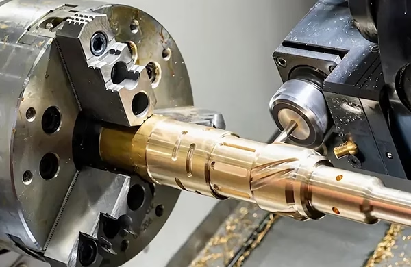
What G17 Actually Controls
One modal code, four places it decides whether the tool cuts where you expect.
Declare the Plane in the Safety Block
G17 is modal. Once it is active, it stays active until something changes it. That is exactly why it gets forgotten. Many CAM posts write G17 at the top of the program and nowhere else, so a mid-cycle restart, a manual MDI move or a subroutine that switched to G18 can leave the controller in the wrong plane.
Put G17 in the safety block, right after G90 absolute positioning and the G21 or G20 unit call. Repeat it before the first circular move or the first G41 block, even when the post already emitted it. The cost of one extra line is nothing. The cost of a gouged cavity in a finished 7075 plate is a re-machined part, a missed ship date and a scrap report.
Our standard header is G17, G40 and G80 together. Cutter comp canceled, canned cycle canceled, plane set to XY. Every machine in the shop starts from the same state, so a program moved between a 3-axis VMC and a 5-axis cell behaves the same way.
- 1Order mattersG90 and units first, then G17, then G40/G80.
- 2Repeat before arcsOne G17 line before the first G02 or G03.
- 3Never assumeA reset or MDI move can leave the plane unchanged from the last job.
Cutter Radius Compensation Lives in the Active Plane
G41 and G42 offset the tool by its radius along the programmed path. That offset vector is calculated in the active plane. With G17 active, the vector sits in XY and the tool shifts left or right in the horizontal plane. Cancel comp, switch to G18 or G19, and the same G41 block now offsets in a different axis pair.
This is where real damage happens. A programmer mills a pocket floor in G17, then turns a part on a right-angle head and switches to G18 for a side wall, and forgets to re-enter G17 before returning to the top face. The first pass after that switch cuts on the wrong side of the profile. Deep gouge, no warning.
Cancel compensation with G40 before any plane change. Lead in and out with a straight move long enough to cover the tool radius, usually at least 50% of the cutter diameter, or the controller alarms on the entry block. Then re-enter G41 or G42 in the new plane. Keep the comp register number in the same block as the G41, not in a separate line, so the offset value and the direction stay paired.
On lathes with live tooling the rule is the same. The ZX plane is G18 on most turning centers, but a sub-spindle or B-axis head may post G17 for face milling. Check the machine manual, not the post.
- 1G40 firstAlways cancel comp before changing plane.
- 2Lead-in lengthAt least half the cutter diameter, straight, no arc entry.
- 3Register on same lineKeep D or H value in the G41/G42 block.
Plane Code, Axis Pair and Typical Use
Match the code to the machine configuration before you post the program.
| Code | Active plane | Comp vector | Typical operation |
|---|---|---|---|
| G17 | XY | X and Y offsets | Pocket floors, face milling, plate work |
| G18 | ZX | Z and X offsets | Turning, side walls with right-angle head |
| G19 | YZ | Y and Z offsets | Side milling on a horizontal or tombstone |
| G17 with G18 | Mixed | Requires G40 between | 5-axis cells with rotary indexing |
Arc Interpolation Needs G17 Before the First G02 or G03
G02 and G03 read the I, J and K words differently depending on the plane. In G17, I is an X offset and J is a Y offset from the arc start. K is ignored. Switch to G18 and J becomes the Z offset while I stays on X. Switch to G19 and K takes over on Y. The controller does not guess. It uses whatever plane is active.
A full-circle arc with I and J set to zero, or an arc whose start and end points are identical, will alarm on most controllers if the plane is wrong. Even when it runs, the tool path bends into the wrong axis and cuts through a wall you wanted to keep. On a deep rib in a 6061 housing, that is a broken 3 mm end mill and a scrapped part.
Post arcs as I, J and K with the full center offset rather than R. The R format is ambiguous for arcs over 180 degrees and controllers resolve it differently. A center-offset arc is longer to read but leaves no room for interpretation. If you must use R, keep it under 180 degrees and add the plane code on the same block as the G02 or G03 so the two are never separated by an operator edit.
G90, G91 and Coordinate Rotation Depend on the Plane
G68 coordinate rotation and G51 scaling operate inside the active plane. Rotate a pattern in G17 and the controller spins it about the Z axis using the XY center you gave. Do the same in G18 and the rotation happens about the Y axis instead. The numbers look valid either way, so nothing alarms. The part is just wrong.
Keep the absolute or incremental mode explicit in the same block as the plane call when you write a subprogram that could be called from either context. G90 G17 on one line removes any doubt. A sub called in G91 that assumes G90 will mirror or stack features in the wrong place, and the error only shows up at inspection.
Before a rotation, position the tool at the rotation center and cancel any active cutter comp. Rotation with comp active moves the offset vector with the path in some controllers and leaves it fixed in others. That difference alone is enough to scrap a hole pattern on a flange with a tight bolt circle.
- 1Rotate in planeG68 spins about the axis normal to the active plane.
- 2Comp off firstG40 before G68, never during.
- 3State the modeG90 G17 in the sub header, not inherited.
Tool Change and Restart Do Not Reset G17 for You
Many controllers keep modal state across a tool change. Others clear it when the operator presses reset, opens the door or runs an MDI command. The behavior varies between Fanuc, Siemens and Heidenhain, and even between machine builders using the same control. There is no safe assumption here.
Treat every restart point as a fresh plane. If your program has a safe restart block per tool, include G17, G40 and G80 in it. Operators who re-enter a program mid-cycle, after a chip jam or a broken insert, then get a known state instead of whatever the last MDI move left behind.
On a 5-axis cell this matters more, not less. A rotary index that moves the part between setups can change what XY means relative to the workpiece. Set the plane from the active work offset and confirm the rotary position before the first cutting move. We keep a short checklist in the setup sheet for every 5-axis job that crosses a rotary index.
Canned Cycles Read the Plane Too
G81, G83, G73 and the rest of the drilling cycles drill along the axis normal to the active plane. In G17 that is Z. In G18 it is Y. In G19 it is X. Most operators only ever see them in G17, which is why the mistake is rare but expensive when it happens on a horizontal or a right-angle head.
Two details bite. First, the R plane and the retract height are measured along the drilling axis, so switching planes changes what the same R value means. Second, G80 must cancel the cycle before any plane change. A cycle left active across a G18 call will repeat the hole at the wrong orientation, or alarm, depending on the control.
For deep holes, peck increments and dwell are not affected by the plane, but the return mode is. G98 returns to the initial level, G99 to the R level. Confirm the mode before you index a fixture, because a G98 retract on a tall part can drag the drill through a clamp if the plane and offset are not the ones you planned.
- 1Axis follows planeG17 drills along Z, G18 along Y, G19 along X.
- 2Cancel before changeG80 in the line before any new plane code.
- 3Check return modeG98 or G99 changes the retract height.
Post-Processor and Simulator Settings Are Part of the Fix
A post-processor that emits G17 once at the top is fine for a single-setup 3-axis job and a liability everywhere else. Configure the post to output the plane code before every circular move, every compensation block and every canned cycle group. It costs a few lines per program and removes the whole class of error.
Match the simulator to the machine. If the verification software assumes G17 stays active through a subroutine and the control clears it on reset, the simulation will not show the crash you are trying to catch. Set the simulator to the same modal behavior as the machine, or verify with the plane explicitly re-declared and treat that as the real path.
Keep a short list of the post settings that matter and check them when a new machine joins the floor. Plane output, comp output with the register on the same block, arc format as IJK, and a safety block that resets the plane at every tool call. Those four settings catch most of the G17 problems before the program ever reaches a spindle.
- 1Plane before arcsOutput G17 ahead of any G02/G03.
- 2IJK arcsAvoid R format for arcs over 180 degrees.
- 3Safety block per toolG17, G40, G80 at every tool call.
Common Questions About G17
Is G17 always the default plane on a milling machine?
On most vertical machining centers the control powers up in G17, and many builders list it as the default in the manual. That is not the same as guaranteed.
A reset, a power cycle during a job, or a macro that sets G18 can change it. Write G17 explicitly in the safety block rather than relying on the power-up state.
What happens if I run G41 in G18 by mistake?
The compensation vector is applied in the ZX plane instead of XY. The tool offsets along a different axis pair than the one you programmed.
The result is usually an undercut wall or a gouged floor. Some controllers alarm if the lead-in move does not suit the plane, but many will simply cut the wrong path without complaint.
Do I need G17 before a drilling cycle?
Yes, if the cycle drills along Z. G81, G83 and similar cycles drill along the axis normal to the active plane.
If the machine is sitting in G18 from a previous operation, the same cycle will drill along Y. Add G17 in the block before the cycle and cancel the cycle with G80 before any plane change.
Should I use R or IJK for arc output?
IJK center offsets are unambiguous. The controller uses the offset from the arc start point, so there is no sign or direction guesswork.
R format is shorter but ambiguous for arcs over 180 degrees, and different controls resolve it differently. For production milling, post IJK and keep R for simple cases under 180 degrees.
Can G17 affect coordinate rotation?
Yes. G68 rotates about the axis normal to the active plane. In G17 the rotation is about Z using the XY center you specify.
Switch to G18 and the same numbers rotate about Y. Cancel cutter compensation with G40 before calling G68, because controllers differ on how comp behaves during a rotation.
How do we stop plane errors across multiple setups?
Put the plane code in a safety block that runs at every tool call, not just at the program top. Include G17, G40 and G80 together.
Set the post-processor to output the plane before every arc, comp block and canned cycle, and set the simulator to the same modal behavior as the machine. The program then carries its own state instead of inheriting it.
Send Us the Part That Keeps Scrapping
Upload a drawing or a STEP file and we will review the geometry, the planes and the setups before quoting. DFM feedback and a quote within 12 hours.
12-hour quote100% inspection±0.005 mmNDA on request









