
Kashifuji Gear Cutting: 7 Ways to Slash Production Costs
This page is for engineers and buyers who run gearbox and drivetrain parts on Kashifuji-class gear cutting machines. We walk through the seven parameters that actually move cost per good tooth: setup count, tooling, coolant, heat treat timing, material choice and inspection. After reading it you can tell which of these apply to your part, and which ones will not pay back.
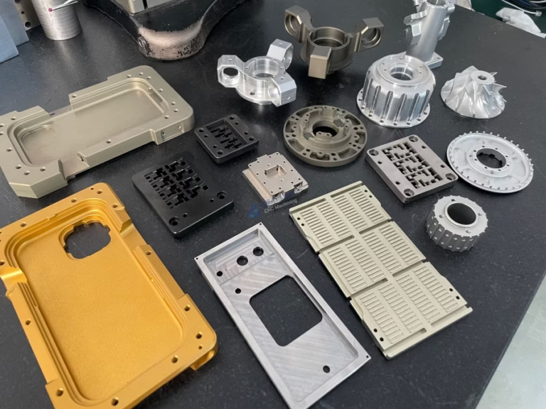
Where Gear Cutting Cost Actually Comes From
Cost per good tooth, not cost per hour, is the number that matters.
Cut the Setup Count Before Touching Speeds and Feeds
Most gear cutting quotes are built from cycle time. That number is easy to measure and easy to argue about. It is also rarely the biggest line item. On a typical spiral bevel or hypoid gear, the hours spent on fixturing, indicating the blank, and proving the first article often exceed the hours of actual cutting. Every extra setup adds its own stack of error. Runout that was 0.01 mm in the chuck can become 0.03 mm after a second op, and that error lands directly in the tooth contact pattern.
This is where a simultaneous five-axis machine earns its place. With a Ø400 mm rotary table and a trunnion, the tooth form and the reference bore can be cut in one setup. The blank stays clamped, so the relationship between the bore, the face, and the tooth flank is fixed by the machine, not by the operator. On gearbox housings and drivetrain parts we see setup count drop from three to one, and the first-article scrap that goes with each re-clamp disappears with it.
There is a limit. Five-axis is not free money. If your part is a simple spur gear with one bore and one keyway, a three-axis machine with a dedicated fixture will beat it on cost and on cycle time. Single-setup five-axis pays back when the part has intersecting features, an angled tooth form, or a tight bore-to-flank relationship that is hard to hold across two ops. Judge it by the number of datums, not by the machine brochure.
Tooling and Coolant: Two Parameters That Are Usually Left Alone
Tool life on gear cutting tools is driven by chip load per tooth, not by surface speed alone. When a hob or a cutter starts to break down, the reflex is to slow the spindle. That usually makes things worse. Lower speed with the same feed per tooth raises the specific cutting force and rubs the edge instead of cutting. A better move is to keep the chipload and reduce the depth, or split the roughing and finishing passes so the finishing tool only removes the last 0.3–0.5 mm.
Coolant is the parameter most shops set once and never revisit. On hardened stainless and titanium, the failure mode is heat at the tool tip, and the fix is directed high-pressure coolant aimed at the contact zone, not a flood that never reaches it. On aluminium and brass, the same high pressure is wasted. Coolant strategy should change with the material group, and the nozzle position should be checked at the start of every run, not just at setup.
There is a tradeoff worth naming. High-pressure through-tool coolant consumes more pump power and more maintenance. On short runs it is hard to justify. On long runs of 17-4PH or Ti-6Al-4V, it typically pays back within the first batch because tool changes and re-cuts drop. We decide per part number, not per shop policy.
Chip evacuation is part of the same decision. Deep tooth spaces trap chips, and a recut chip is the fastest way to chip a carbide edge. Air blast plus a short, controlled coolant pulse often works better than continuous flood.
- 1Keep the chipload, reduce the depthSlowing the spindle with the same feed per tooth rubs the edge and shortens tool life.
- 2Aim the coolantHigh pressure at the contact zone for stainless and titanium; flood is enough for aluminium and brass.
- 3Split rough and finishLeave 0.3–0.5 mm for the finishing pass so the finish tool sees a clean, light cut.
- 4Do not recut chipsAir blast plus a short coolant pulse clears deep tooth spaces better than continuous flood.
Which Gear Cutting Setup Fits Which Part
Use this to decide before the quote, not after the first article.
| Part feature | Setup choice | Why it pays | Watch out for |
|---|---|---|---|
| Spur gear, single bore and keyway | 3-axis plus dedicated fixture | Lowest cycle time and lowest fixturing cost | Fixture must be re-trued between batches |
| Helical gear with angled flank | 4-axis or 5-axis | Tooth form and bore held in one reference | Rotary table runout adds to flank error |
| Hypoid or spiral bevel | Simultaneous 5-axis | Complex tooth form cut in a single setup | Programming and prove-out time is longer |
| Hardened stainless gear | 5-axis plus high-pressure coolant | Heat stays out of the tool tip | Pump power and nozzle maintenance |
| Large housing, 4,000 mm envelope | 5-axis with long travel | Fewer re-clamps on a big casting | Thermal drift over long cycles |
| Prototype, one to five pieces | 5-axis, no soft tooling | No fixture cost to write off | Per-piece cost is higher than production |
Cut Before You Harden, or Grind After. Not Both by Habit
A common cost leak is heat treating at the wrong point in the sequence. If a gear is cut soft, then carburized and hardened, the tooth flank distorts. The distortion has to be removed, and that means a grinding or hard-finishing step with its own setup, its own wheel cost, and its own scrap risk. Some of that is unavoidable on case-hardened gears. Much of it is not.
Where the design allows, cutting the tooth form after hardening with a carbide or CBN tool removes the finishing setup entirely. That works well for through-hardened steels in the 45–55 HRC range and for smaller modules. Above that hardness, tool cost and edge life turn the decision the other way, and grinding is the cheaper route. The point is to make this a deliberate choice from the drawing, not a default that is repeated because it was done that way on the last job.
Distortion also depends on how the blank is held during heat treat. A gear that is quenched while lying flat and unsupported will move differently from one that is fixtured or press-quenched. If the hardening shop is not told what the flank tolerance is, they cannot help hold it. Send the tooth tolerance with the heat treat order.
Material Choice and In-Process Inspection
Material selection changes gear cutting cost more than most engineers expect. Free-machining grades such as 303 stainless and C36000 brass cut cleanly and hold a good flank finish, but they are weaker and are not suitable for loaded gears. Alloy steels like 4140 and 4340 cut well in the annealed state and harden predictably, which keeps the finishing step short. Titanium and Inconel cut hot, wear tools fast, and need the coolant and speed strategy adjusted from the first pass.
The practical rule is to match the material to the load case, then accept the machining cost that follows. Choosing a harder material to gain a small safety margin often adds more cost in tooling and finishing than the margin is worth. If the load case is not clear, it is worth resolving before the material is ordered.
Inspection is the other half. On gear work, checking the tooth form at the end of the run is too late. We monitor the first article against the drawing, then hold a sampling interval through the run, and inspect 100% before shipment. Reports are available on request. This is not a quality slogan. It is what keeps a batch from being re-cut, and re-cutting a hardened gear usually means starting over.
- 1Free-machining grades303 and C36000 cut fast and finish well, but are not for loaded teeth.
- 2Alloy steels4140 and 4340 machine well annealed and harden predictably.
- 3Titanium and InconelPlan for high-pressure coolant and shorter tool life from the first pass.
- 4Inspection timingFirst article, sampling through the run, then 100% before shipment.
Treat DFM as Part of the Gear Cutting Quote
The last cost lever is the earliest one. A DFM review before the first chip is cut catches the features that force extra setups, tight tolerances that do not need to be tight, and tooth forms that could be cut on a smaller machine. On gear work, small drawing changes have large effects. Relaxing a non-functional bore tolerance from ±0.01 mm to ±0.02 mm can remove a finishing op. Adding a relief groove can let a tool exit cleanly instead of being backed out.
We run this review as part of the quotation. It takes hours, not weeks, and it is where most of the savings on a gear job are actually found. Once the process is set and the first article is approved, the cost is largely fixed. The window to change it is before the order.
None of these seven items is exotic. Most of them are decisions that get made by default because no one asked the question. Ask the question at quoting time and the cost per good tooth drops without touching the machine.
Gear Cutting Questions Engineers Ask
Do we need a simultaneous five-axis machine for every gear?
No. Simple spur and helical gears with one bore and one keyway are usually cheaper on a three-axis machine with a dedicated fixture.
Five-axis pays back when the part has intersecting features, an angled tooth form, or a tight bore-to-flank relationship that is hard to hold across two setups. Count the datums first.
What tolerance and finish can you hold on gear work?
We hold ±0.005 mm (±0.0002 in) on machined features, with surface finish from Ra 0.2–0.8 μm on fine finishing down to Ra 1.6–3.2 μm as-machined.
The achievable flank tolerance depends on the tooth form, the material and whether the part is cut soft or after hardening. It is confirmed during DFM review.
Should the tooth form be cut before or after heat treatment?
Cut soft, then grind after hardening, is the safe route for case-hardened gears above roughly 55 HRC.
For through-hardened steels in the 45–55 HRC range and smaller modules, cutting after hardening with carbide or CBN can remove the finishing setup entirely. We compare both routes during quoting.
What is the minimum order quantity for gear cutting?
There is no minimum order quantity. We run from one prototype to 10,000+ part runs.
For one to five pieces we skip soft tooling and cut on five-axis, which avoids fixture cost but gives a higher per-piece price than a production run.
How do you keep gear drawings and tooth data confidential?
Uploads are secure and confidential, and an NDA is available on request before drawings are shared.
We hold ISO 27001:2022 for information security alongside ISO 9001:2015, IATF 16949:2016 and ISO 13485:2016.
How fast can a gear cutting quote and first article come back?
Quotation and free DFM analysis are returned within 12 hours, and production can start within 24 hours of approval.
Parts ship in 3–5 days for most gear work. Historical late-delivery probability is below 2%.
Send the Drawing and We Will Cost the Tooth Form
Upload the gear drawing and we return a quotation plus a free DFM review within 12 hours, with the setup route and finish route spelled out.
12-hour quoteFree DFM review100% inspectionNDA on request









