
7 CNC Welding Techniques to Slash Production Costs
This page is for engineers and buyers who weld machined parts and keep losing margin to joint prep, distortion and rework. We cover seven CNC-based techniques, when each one pays off, and when it does not. Read it before you release the next weldment drawing.
Weld cost is decided before the arc starts
A weldment costs what its joint preparation, fit-up and sequence cost. The arc itself is rarely the problem.
CNC pre-weld preparation with automated chamfering
Manual edge preparation is the first place a weldment budget leaks. A grinder produces a bevel angle that drifts run to run, and the root face varies with operator pressure. The welder then compensates, usually with more filler than the joint needs. Extra filler means more heat input, more shrinkage, and a distortion correction step later.
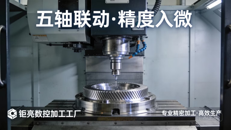
CNC-machined weld edges remove that variable. We cut J-grooves, double-V bevels and U-grooves directly in the machining program, holding bevel angle and root face to ±0.05 mm on a five-axis center. The joint geometry in the CAD model is the joint geometry on the bench. Nothing is left to a hand tool.
The payoff is not only a cleaner bead. A consistent root face lets you specify a narrower groove, which cuts filler consumption and arc-on time. It also makes penetration predictable, so you stop adding weld size as insurance against an unknown root gap. On parts under 200 mm, the machining time added is usually a few minutes.
- 1Use it whenThe part already goes through a CNC operation, or the joint will be welded under a procedure that fixes penetration.
- 2Skip it whenThe joint is a simple fillet with a generous leg size and no distortion requirement.
- 3Drawing noteState "CNC-prepared weld edges" and call out bevel angle and root face on the section view.
Split complex weldments into machinable sub-components
Engineers often design a weldment as one closed assembly because it looks simpler on the drawing. In the shop, that closed shape is the expensive part. Deep welds inside a box section are hard to reach, need special torches, and cannot be inspected properly. A single out-of-position pass can scrap the whole assembly.
The alternative is to split the assembly into two or three sub-components that are welded open, then closed by a small final weld. That means the critical joints are done in the flat position with good access. It also lets you machine a locating step or a tongue-and-groove at the split line, which self-aligns the parts and removes the need for a large fixture.
Splitting does add one weld seam and one fit-up operation. We compare that against the cost of the access tooling, the rework risk and the inspection difficulty on the closed version. For box frames, manifolds and housings with internal ribs, the split version usually wins. For a simple two-plate bracket it never does.
- 1Self-locating featuresA 0.5 mm machined step or a tongue-and-groove at the joint removes most fit-up time.
- 2Watch the datum chainEach split adds a tolerance stack. Machine the final critical faces after welding.
Heat sink control with CNC-machined fixtures
Thin-wall weldments move because heat has nowhere to go. The usual response is to reduce amperage, which slows travel speed and puts more heat into the part, not less. Copper or aluminium backing bars and chill blocks pull heat out of the joint instead, and the weld stays where you put it.
The catch is that a chill block only works if it touches the part. Hand-cut bars leave gaps and burn marks. We machine the chill profile into the fixture, matching the part contour to within ±0.05 mm, so contact is consistent along the whole seam. The same fixture can carry clamps, stops and a copper insert at the root.
This matters most on stainless and aluminium, where thermal conductivity and distortion behave differently. On 304 stainless, a machined copper backing bar lets us keep a full-penetration root without a purge setup on some geometries. On 6061 aluminium, a machined chill block reduces the post-weld straightening that would otherwise be needed.
- 1Best candidatesThin-wall tubes, long seams, and parts with a flatness callout under 0.2 mm.
- 2Material choiceCopper for maximum heat pull, aluminium for lower cost and lower contamination risk.
- 3Not worth itThick-section parts that can absorb heat without visible movement.
Weld sequencing planned in the CAM program
Most weld distortion is not a metallurgy problem. It is a sequence problem. A welder who runs all four corners of a frame in order will pull the frame into a parallelogram, then spend an hour pulling it back. The same four welds, run in a balanced order with cooling between passes, finish square.
We plan the sequence in the same environment as the machining program, using the same datums. Stitch patterns, back-step direction and pass order are written down and given to the welder, not improvised at the bench. On parts with a tight flatness callout, the sequence is validated on a first article before the run starts.
Sequencing costs nothing but planning time, which is why it is the first technique we apply. It also makes the result repeatable across shifts. If one welder gets a square frame and the next gets a twisted one from the same drawing, the sequence was never defined.
- 1Back-step weldingSegment each pass in the opposite direction of travel to spread heat along the seam.
- 2Balanced pairsWeld opposite sides of a symmetric part in the same pass order.
Which technique fits which part
Use this to decide which of the seven techniques to apply to a specific weldment.
| Part condition | First technique to apply | Expected effect |
|---|---|---|
| Bevel angle varies run to run | CNC pre-weld preparation | Stable root face, less filler |
| Deep internal joints, poor access | Component splitting | Flat-position welds, easier inspection |
| Thin wall, flatness under 0.2 mm | Machined chill fixtures | Less post-weld straightening |
| Long seams on a frame | Weld sequencing in CAM | Square parts, repeatable across shifts |
| High-mix low-volume runs | Hybrid repair and modification | Reuse existing weldments |
| Tight tolerance after welding | Post-weld finish machining | Datum restored in one setup |
Post-weld finish machining instead of straightening
When a weldment comes out of the fixture out of tolerance, the default response is to press it straight. That is slow, it is hard to control, and it can crack a weld. A better option is often to leave stock on the critical faces, weld, then machine them in one setup after the part has cooled.
This is the same logic as rough-then-finish on a single part. The weld is the roughing operation. The final machining pass restores the datum, the bore alignment and the flatness without fighting residual stress. Because the cut is small, tool load is low and the surface finish is easy to hold.
The technique needs the drawing to allow it. If the critical face is finish-machined before welding, no amount of process control will recover it. Add 0.3 to 0.5 mm of stock on faces that will be machined after welding, and mark them on the drawing.
- 1Stock allowance0.3–0.5 mm is usually enough for stress relief plus a clean-up cut.
- 2Order of operationsMachine datums, weld, stress relieve if specified, then finish machine.
In-process measurement of the welded assembly
A weldment that is checked only at final inspection is a weldment that hides its cost until the end. By then, rework is at its most expensive. Measuring key features after welding, before finish machining, moves the discovery point earlier and keeps the value of the part low while it can still be corrected.
In practice this means a CMM or a portable measurement check on the features that drive assembly. If the part is inside tolerance, it moves on. If it is out, we know which seam pulled and can correct the sequence for the rest of the run. That data feeds back into the CAM plan.
For medical and automotive work, the same records support traceability. We inspect every part before shipment, and we keep raw material, in-process and final inspection records that can be shared on request.
- 1What to measureDatum faces, bore centers and any feature that mates with another part.
- 2What not to measureSurfaces that will be machined again after this check.
Hybrid repair and modification of existing weldments
Repair is the cost center most teams ignore. A worn casting, a damaged bracket or an obsolete weldment often gets replaced because no one quotes the repair. Machining a repair is usually cheaper than making the part from raw stock, and it is far cheaper than the downtime of a replacement.
The work is straightforward: machine out the damaged area, weld in a patch or build up the surface, then machine back to the original geometry. The key is to machine a clean pocket with a defined edge rather than welding onto a ragged break. That gives a sound joint and a predictable result.
We also use this approach for design changes. If a weldment needs an extra boss or a moved hole, machining and welding the existing part can get a line running again without a full re-make. We quote repair and modification from the same drawing controls as new work.
- 1Good repair candidatesCastings, large weldments and parts with long lead-time material.
- 2Poor candidatesLow-cost parts where the setup time exceeds the price of a new one.
Common questions on CNC welding cost
Can you weld and machine a part in one order?
Yes. We machine the weld prep, weld the sub-components, and finish machine the assembly in the same order. That keeps the datum chain in one place.
For most weldments we run the machining and welding steps as one process plan, so the part does not travel between suppliers.
What tolerance can you hold after welding?
Our machining tolerance is ±0.005 mm on the finished part. What matters after welding is the machining allowance left for the final pass.
If the critical face is finish-machined after weld and stress relief, tolerance is held by the machine, not by the welder.
Which materials do you weld and then machine?
Aluminium 6061, 6061-T6, 5052, 5083, 6082 and 7075; stainless 304, 316, 316L and 17-4PH; steel 1018, 1045, 4130 and 4140; plus titanium TC4 and Inconel.
Material combination matters more than the grade. Welding dissimilar metals needs a procedure check before we quote.
Do you need a welding procedure specification?
If your industry requires one, send it with the drawing. We will confirm whether the joint design and material fit the procedure.
If you do not have one, we will propose a sequence and weld prep based on the drawing and the distortion requirement.
How do you handle distortion on long weldments?
We control it with three steps: machined weld prep, a machined chill fixture, and a defined weld sequence. Post-weld machining cleans up whatever remains.
For parts up to 4,000 mm we machine the final datums after welding, so the starting condition of the weld does not carry into the finished part.
What is the smallest and largest weldment you can take?
There is no minimum order quantity. We run from one prototype to 10,000+ part runs.
Maximum processing size is 4,000 mm, so large frames and bases are within range.
Send the weldment drawing and get a process plan
We review the joint design, weld prep and sequencing, then quote with a DFM note in 12 hours. Uploads stay confidential, and an NDA is available on request.
12-hour quote100% inspectionNo MOQISO 9001 / IATF 16949









