
7 Essential Tips for CNC Cutting Carbon Fiber Without Costly Delamination
Delamination is rarely caused by one mistake. It comes from tool geometry, chipload, support and heat acting together. This guide is written for design engineers and manufacturing managers who need clean CFRP edges on the first run, not after three rework loops.
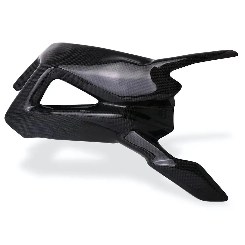
Why CFRP Punishes a Standard Milling Setup
Carbon fiber reinforced polymer is two materials in one. Hard carbon fibers carry the load, and a thermoset resin holds them in place. A cutter has to shear brittle fibers and soft resin in the same pass, at the same feed. Metals do not behave like this, so a program copied from an aluminum job usually fails.
The fibers are abrasive. Uncoated carbide dulls fast, the edge radius grows, and a dull tool stops shearing. It starts pushing. Once that happens the top plies lift away from the laminate and you get delamination, fuzzy edges and resin smear. Tool wear is the leading cause, and it is the easiest one to manage.
Fiber direction adds a second problem. A ply running parallel to the cut behaves differently from a ply at 90°. At the 45° plies the load switches direction mid-cut, and the tool can pull fibers out instead of cutting them. That is why the same program can produce a clean edge on one face and a blown-out edge on the opposite face.
Tip 1: Tool Geometry, Tip 2: Tool Path Strategy
Tip 1 starts with the coating. Chemical vapor deposition diamond on a carbide substrate keeps the cutting edge sharp for far longer than plain carbide. For a one-off prototype, uncoated carbide can survive. For a run of 50 parts or more, diamond coating usually pays for itself in reduced tool changes and steadier edge quality.
Geometry matters as much as coating. A compression cutter has left-hand flutes at the tip and right-hand flutes along the body. The opposing spirals push the top and bottom plies toward each other instead of peeling them apart. On laminates under 3 mm thick, that single change often removes delamination at the perimeter.
Flute count and helix angle follow the same logic. Two or three flutes give more chip room than a four-flute metal cutter, and a low helix reduces the axial force that lifts plies. On thin plate, a high helix can act like a wedge.
Tip 2 is about direction. Climb milling puts the maximum chip load at the start of the engagement, where the fiber is still supported by the surrounding material. Conventional milling rubs first and cuts later, which is exactly the condition that generates heat and pull-out.
For deep pockets, trochoidal paths keep radial engagement small and let the tool cut at a consistent load instead of stalling in corners. Control the entry too. A helical ramp or a pre-drilled pilot hole avoids plunging straight into the laminate, and a small chamfer at the exit face stops the last fibers from tearing out.
Starting Parameters for CFRP End Milling
Treat these as a starting window, not a recipe. Ply count, resin type and tool coating shift the numbers.
| Operation | Tool | Speed | Feed note |
|---|---|---|---|
| Perimeter trim, 2 mm plate | Ø6 mm compression, 2 flute | 12,000–18,000 rpm | 0.05–0.10 mm/tooth, climb |
| Pocket roughing | Ø8 mm diamond-coated, 3 flute | 10,000–14,000 rpm | Trochoidal, 8% radial step |
| Deep slot, 20 mm depth | Ø6 mm tapered, 2 flute | 9,000–12,000 rpm | Depth 1×D per pass |
| Drilling Ø4 mm | Diamond-coated drill, 8×D | 6,000–9,000 rpm | Peck 1×D, air blast |
| Edge finishing | Ø10 mm shear, 3 flute | 14,000–20,000 rpm | 0.03 mm/tooth, single pass |
Tip 3: Chipload and Cooling, Tip 4: Workholding
Tip 3 is about heat. Too light a chipload is a common mistake. When the feed is too low, the edge rubs instead of cutting, and the resin softens. Soft resin no longer holds the fibers, so they smear. A chipload of 0.05–0.10 mm per tooth for a Ø6 mm cutter is a reasonable starting window, and the correct value is the one that produces chips rather than dust.
Cooling is a choice between air blast and minimum quantity lubrication. Flood coolant is usually wrong here. Water-based coolant can be absorbed by an exposed resin edge and it complicates cleanup. For most CFRP work, a directed air blast or a light oil mist removes the dust and carries away enough heat. Dust extraction at the nozzle matters for operator safety as well.
Tip 4 decides whether any of the above can work. Carbon fiber plate is thin and stiff, so any unsupported span will chatter. Chatter leaves a mark, and the mark is where delamination starts.
Vacuum fixturing holds the whole underside of the plate, which is the most reliable option for flat work. Leave a sacrificial backing layer under the part so the last ply is supported as the tool breaks through. For contoured or thick parts, a machined pocket in a rigid fixture locates the part and clamps it without point loads. Avoid clamping directly on the laminate edge. It distorts the plate and pre-loads the plies.
Tip 5: Thermal Control, Tip 6: Complex Geometry, Tip 7: Inspection
Tip 5 is a scheduling decision as much as a machining one. Spreading the cut into two or three lighter passes keeps the cutting zone cooler than one heavy pass. If the part allows it, machine the perimeter first, then the pockets, so the structural edge is finished before the tool has any wear on it.
Peel ply and surface preparation also affect what you measure after machining. A part that was bagged cleanly will show a sharper edge than one with resin-rich skin. If the drawing allows, trim the peel ply before the final finish pass instead of after.
Tip 6 covers geometry that a three-axis machine cannot reach. On a five-axis machine the tool can be tilted so the cutting edge meets the fibers at a consistent angle around a contoured part. Tapered tools reach deep ribs and pockets with a smaller tip and a stiffer body, which reduces deflection at the bottom of a pocket.
Tip 7 is where delamination gets caught. Visual inspection under low-angle light finds lifted plies at the top edge. A 10× to 30× loupe or a bench microscope reveals the resin smear that a naked eye misses. For a first article, cross-section a sample cut and measure the delamination depth against the drawing allowance.
Ultrasonic testing is the right tool for internal voids and ply separation that no surface check will show, and it is worth the cost on structural parts. Record the tool, the program revision and the measured edge quality together. When a later batch drifts, that record tells you whether the cause is the tool or the setup.
Common Questions on CFRP Machining
How thick can you machine in one pass?
For perimeter trimming on plate up to about 3 mm, a compression cutter can often take the full depth in one pass, which gives the best edge.
Above that, step down to roughly 1× tool diameter per pass. The extra time is cheaper than a rework loop.
Do you need diamond tooling for a single prototype?
No. For one or two parts, a sharp uncoated carbide cutter with the right geometry will finish the job.
Diamond coating earns its cost when the same cutter has to hold edge quality across tens of parts, because a dulling edge is what starts delamination.
Can you use flood coolant on carbon fiber?
Air blast or a light oil mist covers most CFRP jobs. It clears dust and limits heat without soaking an exposed edge.
Flood coolant is not automatically wrong, but it needs a specific reason on the drawing, and the part must be dried properly afterward.
What tolerance can be held on carbon fiber parts?
We machine to ±0.005 mm (0.0002 in) on the features that the fixture can support rigidly.
CFRP has a different thermal expansion behavior than metal. On long parts, hold the drawing tolerance against a stable temperature rather than an assumed room condition.
How do you check for delamination after machining?
Start with low-angle light and a 10× to 30× loupe along the cut edge. Look for lifted plies and resin smear.
For structural parts, add ultrasonic testing or a cross-section on the first article. Surface inspection alone will not find internal voids.
Can carbon fiber be machined on a three-axis machine?
Yes, for flat plate, simple pockets and drilled holes. Most CFRP work fits a three-axis setup.
Contoured parts, deep ribs and features that need the tool tilted along the fiber direction are better on a five-axis machine.
Send Us Your CFRP Part and Drawing
Upload a STEP file and we return a quote, a DFM analysis and a tooling recommendation within 12 hours. Prototype quantities and 10,000+ part runs both run on the same process controls.
12-hour quote±0.005 mm100% inspectionNDA on request









