
Accessory CNC Machining Services for Small, Critical Parts
Accessories are the parts that decide whether an assembly closes, seals and survives vibration: brackets, sensor housings, custom fasteners, connectors, clips, spacers. This page is for design and manufacturing engineers who need to quote them. Read it to judge which features drive cost, when 5-axis pays off, and what to put on the drawing.
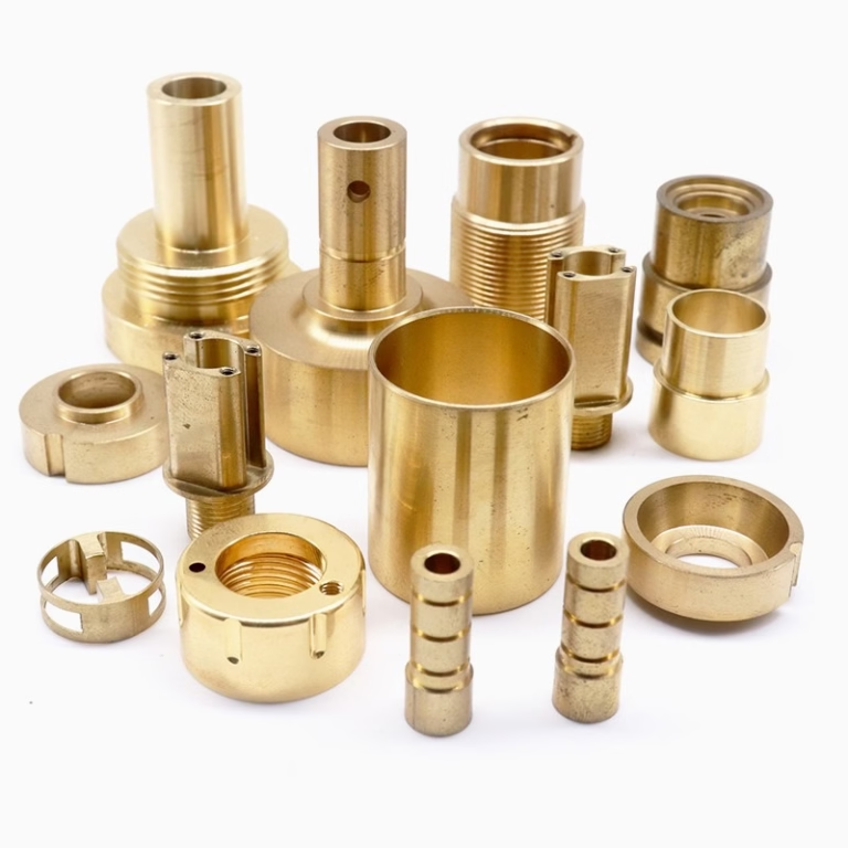
What makes accessory machining different
Small parts, low stiffness, tight interfaces, and a finish that the end user actually touches.
Why small accessory parts are harder than they look
An accessory is rarely a simple block. It is a bracket with an offset boss, a housing with a connector cutout and a gasket groove, or a spacer that has to sit flat against two surfaces at once. The features are small, and small features sit close to each other. That is where the trouble starts.
Take a typical sensor housing in 6061-T6 at 38 × 26 × 18 mm with a 1.2 mm wall. Cutting forces from a Ø8 mm end mill would push that wall out of position. So we step down to a Ø3 mm tool, then Ø1.5 mm for the internal corner radii. Smaller tools mean lower feed per tooth, more passes, and more heat in the part. Cycle time goes up, and so does the risk of chatter.
Thin walls also move after machining. A 1 mm aluminium wall relieved from one side will bow 0.02–0.05 mm as residual stress balances out. If the drawing calls for ±0.05 mm on that wall, the part may pass on the machine and fail after anodizing. On accessory work we usually ask for a stress-relieved or pre-machined blank, and we leave 0.3 mm for a finishing pass after the part has cooled.
Then there is access. A mounting hole on the underside of a bracket, plus a tapped hole on the side face, plus a bore through the top: three directions. On a 3-axis machine that is three setups and three fixtures. Each re-clamp adds positional error and handling time.
- 1High feature densityMany small holes, slots and radii in one small envelope.
- 2Low stiffnessWalls under 2 mm deflect under normal cutting loads.
- 3Multiple directionsFeatures on 3+ faces force repeated setups on 3-axis work.
- 4Fit-critical interfacesA 0.03 mm shift can stop an assembly from closing.
Five-axis setups, and when they are not worth it
With 16 simultaneous 5-axis machining centers, we machine angled ports, undercuts and cross-drilled holes in one setup. No cumulative fixture error, no re-datum between operations. For a one-off housing with internal channels and three angled faces, that single setup is often the difference between a part that fits and a part that needs rework.
But 5-axis is not automatically the cheaper route. On a simple flat bracket with two holes and a bend relief, a 3-axis machine with a soft jaw runs faster and costs less. The question is feature count and orientation spread. If all critical features are reachable from one direction, use 3-axis. If the part needs four or more distinct orientations and the tolerances stack across them, 5-axis usually wins on total cost.
We also use mill-turn centers for accessories that are basically turned parts with milled flats: standoffs, threaded inserts, retaining pins, custom fasteners. One machine turns the OD, faces the end, and mills the hex or slot without losing concentricity.
For a batch of 10,000 small clips, the math changes again. A dedicated fixture on a 3-axis machine with a pallet changer can beat a 5-axis cycle once the fixture cost is amortized. We quote both routes when the volume justifies it.
Setup and process choice by accessory type
Use this as a first filter before requesting a quote.
| Part type | Typical features | Suggested process | Watch out for |
|---|---|---|---|
| Flat bracket | 2–6 holes, edge radii | 3-axis, soft jaws | Flatness after bending relief |
| Sensor housing | Pocket, gasket groove, port | 5-axis or 3-axis + fixture | Wall deflection, seal face finish |
| Custom fastener | Thread, hex, shoulder | Mill-turn | Thread concentricity to shoulder |
| Connector shell | Cavities, keyways, plating | 4-axis or 5-axis | Plating build-up on mating faces |
| Spacer / standoff | Turned OD, milled flat | Mill-turn or 4-axis | Perpendicularity of flat to axis |
| Clip / retainer | Thin section, spring form | 3-axis with support | Spring-back after machining |
| Manifold block | Cross-drilled channels | 5-axis | Burr at channel intersections |
What tolerance to actually call out
Our machines hold ±0.005 mm on critical features, and we can inspect to that level. That does not mean every dimension on an accessory drawing should carry it. Tight tolerances everywhere raise cost, slow inspection, and often cause parts to be rejected for variation that never mattered in the assembly.
A practical approach: define the interface dimensions that control fit. A bore that receives a bearing or a shaft, a bolt circle that must align with a mating plate, a gasket groove depth that sets seal compression. Put a real tolerance on those, and leave general dimensions to a title-block tolerance such as ±0.1 mm.
Surface finish matters as much as size on accessories. A gasket face at Ra 3.2 μm may not seal; Ra 0.8–1.6 μm is a common target for sealing surfaces. We can reach Ra 0.2–0.8 μm on functional faces when the geometry allows, but the tool path gets denser and the cycle longer.
Geometric callouts do more work than tight linear tolerances on thin parts. Position and profile tolerances control the relationship between features, which is what usually breaks the assembly. Flatness on a mounting face and perpendicularity between a bore and its seating face solve more real problems than a blanket ±0.02 mm.
- 1Interface dimensionsTight. These decide whether the part assembles.
- 2General dimensionsTitle-block tolerance. ±0.1 mm is usually enough.
- 3Sealing facesRa 0.8–1.6 μm, flatness called out explicitly.
- 4Non-critical edgesLeave as machined at Ra 1.6–3.2 μm.
Material and finish choices for accessories
Aluminium covers most accessory work: 6061-T6 for general brackets and housings, 7075 for high-load clips and fittings, 2024 where fatigue matters, 5052 and 5083 for formed or welded sheet parts. Aluminium machines fast, anodizes well, and keeps weight down, which is usually the point of an accessory.
Stainless 303 and 304 handle outdoor and wash-down environments. 316L for medical and marine. 17-4PH when you need strength plus corrosion resistance in a small section, such as a latch pin or a spring clip. Copper and brass, including C36000 and beryllium copper, show up in contacts, shielding and spring elements where conductivity or spring rate is the function.
Titanium TC4 (Ti-6Al-4V) and Inconel appear on aerospace and high-temperature accessories. Both are slow to cut and hard on tooling, so keep the geometry simple and expect a higher piece price. On the plastic side, POM and PEEK are common for insulators and wear pads; PEEK holds up in high-temperature and chemical exposure but costs far more than POM.
Finishing is where accessory supply chains usually break down. Anodizing for color and wear, electroless nickel or zinc for corrosion, silver and gold plating for conductivity, laser marking for labels down to 1.5 mm character height. If these steps sit with separate vendors, the part travels, gets re-packed, and picks up scratches. We keep finishing and inspection in the same flow so the part does not leave the chain between operations.
Inspection and documentation for small parts
Accessories are hard to inspect because the features are small and the tolerances are tight. A Ø1.5 mm hole at ±0.02 mm is not something you check with calipers. We use vision systems, pin gauges, optical comparators and CMM programs written for the specific geometry.
Every part gets 100% inspection before shipment, with raw material verification, in-process checks and a final inspection. That last step is where we catch plating build-up, burrs at channel intersections and laser marks that landed off-center. Reports are available on request, including dimensional data and material certificates.
We work to ISO 9001:2015, IATF 16949:2016, ISO 13485:2016 and ISO 27001:2022. For automotive and medical accessory programs, that means the process controls and traceability are already in place rather than bolted on after the first audit.
Burrs deserve a specific mention. On a connector shell or a manifold block, a burr at an internal intersection can block flow or damage a mating pin. Deburring is a planned operation, not a cleanup step. We specify tumbling, thermal deburring or hand finishing based on where the burr sits and how accessible it is.
Questions engineers ask about accessory machining
Can you machine an accessory from a single prototype to a 10,000+ part run?
Yes. There is no minimum order quantity. We machine one-off prototypes and production runs above 10,000 pieces on the same equipment, with the same inspection standard.
For higher volumes we build dedicated fixtures and may move the part from a 5-axis cycle to a 3-axis pallet setup if that lowers piece cost without losing tolerance.
How do you hold ±0.005 mm on a thin-walled housing?
We control the blank first. Pre-machining and stress relief reduce movement, then we leave 0.3 mm on the walls for a finishing pass after the part reaches thermal equilibrium.
Tool selection matters too. Small-diameter end mills with higher helix angles, reduced radial engagement and lighter depths of cut keep deflection inside the tolerance band.
What is the smallest feature you can machine on an accessory?
Internal corner radii down to 0.5 mm are routine with micro tooling. Holes below Ø1 mm are possible but need a straight approach and a depth-to-diameter ratio under about 4:1.
Laser marking supports a minimum character height of 1.5 mm. Below that, legibility drops and we recommend a different labeling method.
Can you match a specific anodize color across repeat orders?
We offer clear, color, hardcoat and conductive anodizing. Color matching is done against a physical sample or a defined reference, not from a screen image.
Send the target sample with the RFQ. We will confirm the achievable range before production rather than after.
How do you handle confidentiality on accessory designs?
Uploads are secure and confidential. We sign an NDA on request before reviewing drawings or CAD files.
We operate under ISO 27001:2022 for information security, so document handling and access control follow a defined process.
What do you need for a quote on an accessory part?
A 3D file plus a 2D drawing with tolerances, material, finish and quantity. If the drawing is not ready, send the 3D model and note the critical interfaces.
We return a quotation and a free DFM analysis within 12 hours, and production can start within 24 hours of approval.
Send your accessory part for DFM review
Upload the model and drawing. We will flag thin walls, tight features and finish risks before the first chip is cut.
12-hour quoteFree DFM analysis100% inspectionNDA on request









