
Aero CNC Machining Service
This page explains how aerospace parts differ from general CNC work and how to judge whether a shop can hold them. It is written for design and manufacturing engineers sourcing aero CNC machining service. Read it and you will know which features drive cost, which tolerances are realistic, and what to verify before releasing a drawing.
What Makes Aerospace Machining Different
Aero parts are not hard because they are small. They are hard because weight, strength, and traceability all pull in different directions at once.
Material Choice Drives Every Other Decision
Aero work starts with the alloy, not the geometry. Aluminum 7075 machines cleanly and gives high strength per kilogram, so it dominates brackets, ribs, and fittings. 6061-T6 is easier to weld and cheaper, which suits non-structural housings and test rigs. Titanium TC4 (Ti-6Al-4V) offers better temperature resistance but cuts roughly four to six times slower than aluminum and eats tooling, so it belongs on parts where the thermal load justifies the cost.
Nickel alloys such as Inconel are the opposite case. They hold strength at temperatures where aluminum has already lost most of it, which is why they appear in engine-adjacent hardware. They also work-harden quickly, so shallow depths of cut, sharp tooling, and generous coolant flow are not optional. We machine Inconel on rigid 5-axis platforms with high-pressure coolant rather than on lighter machines.
Carbon fiber and other composites change the problem again. The fibers are abrasive and the resin can delaminate if the tool pushes instead of shears. That means diamond-coated cutters, controlled feed per tooth, and dust extraction at the cut point. If a drawing mixes composite panels with machined metal inserts, plan the sequence so the metal work happens before the composite is bonded, not after.
- 1Aluminum 6061 / 7075Fast to cut, good strength-to-weight, the default for structural brackets.
- 2Titanium TC4High temperature strength; slow cutting, higher tool wear, higher cost.
- 3InconelHot-section hardware; work-hardens, needs rigid setups and coolant.
- 4Carbon fiberAbrasive and delamination-prone; use diamond tooling and extraction.
Why Five-Axis Setups Reduce Risk on Aero Parts
Many aero features are not reachable in one orientation. Angled bosses, contoured pockets, and bolt-hole patterns on curved flanges all force a three-axis machine into multiple re-fixturings. Each re-fixture adds a datum shift. On a part with a ±0.005 mm tolerance stack, that shift can consume the entire budget before a single chip is cut.
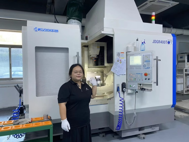
Simultaneous 5-axis machining solves this by keeping the tool normal to the surface and reaching the feature without releasing the part. We run 16 simultaneous 5-axis machining centers with a Ø400 mm rotary table, which covers most airframe brackets and housings. Travel options include 750 × 1,150 × 550 mm and 600 × 600 × 600 mm envelopes, plus a 4,000 × 400 × 150 mm platform for long, slender parts such as stringers and rails.
Not every part needs five axes. Flat plates with through-holes and simple profiles are cheaper on a three-axis mill, and we keep 27 of them for exactly that work. The judgment call is whether the feature geometry forces multiple setups. If it does, five-axis is usually the lower-risk route even when the per-hour rate is higher.
Machine Selection by Part Type
A rough guide to which platform suits which geometry. Final routing depends on the drawing.
| Part type | Typical platform | Why |
|---|---|---|
| Flat plate, simple holes | 3-axis mill | One setup, no compound angles, lowest cost |
| Angled bosses, contoured pockets | 5-axis simultaneous | Reaches features without re-fixturing |
| Rotational fittings | Mill-turn center | Turning and milling in one setup |
| Long stringers, rails | 4,000 mm travel machine | Envelope up to 4,000 × 400 × 150 mm |
| Thin-wall housings | 5-axis, short rigid tooling | Limits deflection and chatter |
Thin-Wall and Distortion Control
Aero design pushes toward thin walls to save weight. The machining problem is that a thin wall deflects under cutting force, then springs back and leaves a tapered surface. Tool pressure also induces residual stress that moves the part after it is unclamped, so a dimension that measures correctly on the machine can drift out of tolerance overnight.
We handle this with shorter, more rigid tools held at effective angles, which keeps radial deflection low. Light depths of cut and higher spindle speeds remove material with less force per pass. Where a wall is very thin, we leave a controlled allowance and take a finishing pass after the part has relaxed. On some parts, a stress-relief step between roughing and finishing is the difference between holding tolerance and chasing it.
Fixturing matters as much as the cutter. Vacuum plates and low-melt holding compounds support the wall from behind instead of clamping it. For parts with a large open face, we sometimes machine a soft jaw that matches the contour, so the clamping load spreads over the whole surface rather than a few points.
Tolerances, Surface Finish, and What to Specify
Our general machining tolerance is ±0.005 mm (±0.0002 in) on critical features. That is a real number, not a marketing figure, and it applies to features that are reachable and stable in the setup. Tightening a non-critical dimension to the same value adds inspection time and cost without improving function.
Surface finish follows the same logic. As-machined surfaces run Ra 1.6–3.2 μm, which is fine for most internal brackets. Sealing faces and bearing bores often call for Ra 0.8–1.6 μm, and a few fluid-contact or optical surfaces need Ra 0.2–0.8 μm. If a drawing calls for a fine finish over a large area, expect more finishing passes and a longer cycle.
Threads, hole callouts, and edge breaks deserve attention before release. A 0.3 mm edge break on a thin titanium rib is not cosmetic; it removes a stress riser. On the other hand, specifying a tight positional tolerance on every hole in a pattern is usually unnecessary. Identify the holes that locate the part and let the rest follow the general tolerance block.
- 1General tolerance±0.005 mm on reachable, stable features.
- 2Standard finishRa 1.6–3.2 μm as machined, suitable for most internal parts.
- 3Fine finishRa 0.2–0.8 μm for sealing and fluid-contact surfaces.
- 4Edge breaksSpecify on thin ribs and fatigue-critical edges to remove stress risers.
Inspection and Documentation
A tolerance claim is only as good as the inspection behind it. Every part we ship goes through 100% inspection: incoming raw material check, in-process monitoring during cutting, and a final dimensional inspection before packing. Inspection reports are available on request, and we can supply first-article documentation for new programs.
For aero work, traceability usually matters as much as the dimension. Material certificates, heat lot numbers, and process records should travel with the part. If your quality system requires PPAP-style documentation or specific report formats, say so at quoting stage so the paperwork is planned into the job rather than added afterward.
Our quality system is certified to ISO 9001:2015, IATF 16949:2016, ISO 13485:2016, and ISO 27001:2022. The information security certification matters when drawings and models are exchanged digitally. Uploads are handled as confidential, and we sign NDAs on request.
From Drawing to Shipped Parts
Indicative sequence. Actual steps depend on part complexity and documentation needs.
| Stage | What happens | Output |
|---|---|---|
| Quote and DFM | Drawing review, free DFM analysis | Quote and manufacturability notes in 12 hours |
| Setup | Fixture design, tool selection, first article | Verified setup and inspection plan |
| Machining | Roughing, stress relief if needed, finishing | Parts cut to drawing tolerance |
| Inspection | Raw material, in-process, final dimensional check | 100% inspected parts, reports on request |
| Shipping | Protective packing, documentation | Parts ship in 3–5 days |
Choosing a Supplier: What to Verify
Ask what machines the shop actually owns, not what it can broker. A supplier with no five-axis capacity will sub-contract your part, and that adds a handoff where tolerance and schedule control weaken. We run 127 high-precision CNC machines across three wholly-owned plants in Dongguan and Singapore, with 16 five-axis centers, 12 four-axis mills, 16 mill-turn centers, and 27 three-axis machines. That mix matters because it lets us route each feature to the right platform.
Ask how inspection is done and who signs the report. A shop that inspects only the first article and then ships the rest on trust is a different risk profile from one that checks every part. Ask about material certification and whether heat lot records are kept.
Finally, ask about communication during the job. A first-article photo and a dimensional report before the run continues will catch problems earlier than a finished shipment. We quote and return free DFM analysis within 12 hours, and production can start within 24 hours of approval. There is no minimum order quantity, so a single prototype and a 10,000-part run go through the same process.
Frequently Asked Questions
What tolerance can you actually hold on aerospace parts?
Our general machining tolerance is ±0.005 mm (±0.0002 in) on critical features. That applies to features that are reachable and stable within the setup.
Very thin walls, deep bores, and long slender parts may need a wider tolerance or additional operations. We flag that during DFM review rather than after the first article.
Which materials do you machine for aero work?
Aluminum 6061, 6061-T6, 2024, 5052, 5083, 6063, 6082, and 7075 are common. Titanium grades include TA1, TA2, and TC4 (Ti-6Al-4V). We also machine Inconel, magnesium AZ31B and AZ91D, plus stainless grades such as 17-4PH.
Carbon fiber and engineering plastics including PEEK and POM are available where the application allows.
Do you sign an NDA before receiving drawings?
Yes. We sign NDAs on request, and uploads are treated as secure and confidential.
If your program requires a specific agreement template, send it with the RFQ so it can be reviewed at quoting stage.
How fast can you quote and start production?
Quotation and free DFM analysis are returned within 12 hours. Production can start within 24 hours after approval.
Parts typically ship in 3–5 days. Historical late-delivery probability is below 2%.
Can you handle both prototypes and production volumes?
Yes. There is no minimum order quantity. We machine from one prototype to 10,000+ part runs using the same process and inspection standard.
For production programs, we can supply first-article documentation and inspection reports on request.
What finishing options are available after machining?
Anodizing in clear, color, hardcoat, and conductive types; electroless nickel, zinc, silver, and gold plating; powder coating and black oxide; bead blasting, tumbling, brushing, and polishing.
Laser marking and engraving are available with a minimum character height of 1.5 mm.
Send a Drawing, Get a Quote and DFM Notes
Upload your model and we will return a quote with manufacturability feedback within 12 hours. One prototype or 10,000 parts, same process.
12-hour quoteFree DFM analysis100% inspectionNDA on request









