
AlSi10Mg 3D Printing: 7 Secrets to Master Strong Parts
This guide covers the seven process decisions that separate a good-looking AlSi10Mg build from one that survives load testing. It is written for design and manufacturing engineers who already run laser powder bed fusion and need to judge where strength is actually lost. Read it and you will know which parameters to lock, which ones to negotiate, and when post-processing is worth the extra step.
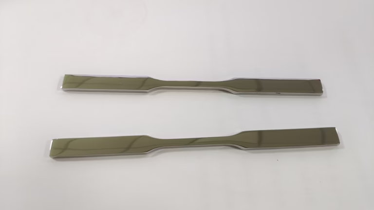
Where AlSi10Mg Strength Is Actually Decided
Strength in AlSi10Mg is not one parameter. Seven decisions form a chain, and the weakest link sets the result.
Powder Chemistry and Particle Size Distribution
AlSi10Mg is a near-eutectic aluminum-silicon alloy, and that is exactly why it prints so well. Silicon sits close to 10 percent, which lowers the melting range and gives the melt pool good fluidity. Hot-cracking susceptibility drops, so thin walls and sharp internal corners are less likely to tear during solidification. None of that helps if the powder itself is out of specification.
Particle size distribution drives layer quality. For L-PBF, most machines run a tight cut in the 15–45 μm band. A wide distribution packs unevenly, and the laser sees a different absorption profile from one layer to the next. Spherical gas-atomized powder flows better and spreads into a flatter bed. Irregular or satellited particles create voids that survive all the way through the build.
Oxygen and moisture are the quiet killers. Aluminum oxide films on particle surfaces raise the local melting point and block bonding between adjacent tracks. Aluminum powder is also hygroscopic, so water picked up in storage dissociates in the melt pool and leaves hydrogen porosity. Those pores act as crack initiation sites under fatigue. Buyers should ask for batch chemistry certificates and evidence that powder was stored dry and sieved between jobs.
Reusing powder is normal in production, but track the number of cycles. Oxygen content creeps upward each time, and the PSD shifts as fines are consumed. A batch that passed at cycle one may not pass at cycle fifteen. At GreatLight we verify incoming chemistry and keep sieving records per batch, because a powder problem cannot be fixed downstream by any amount of laser tuning.
- 1Tight PSD15–45 μm for most L-PBF platforms, verified per batch
- 2High sphericityGas-atomized powder spreads into a more even layer
- 3Low oxygenOxide films block track-to-track bonding
- 4Cycle trackingOxygen rises and fines are consumed on reuse
Laser Power, Scan Strategy and Full Density
Density is the first gate to mechanical strength, and it is set at the melt pool. Volumetric energy density, usually written in J/mm³, combines laser power, scan speed, hatch spacing and layer thickness into one number. Push it too high and the melt pool becomes unstable, keyholing traps gas bubbles, and you get porosity that no heat treatment can remove.
Too little energy is the opposite failure. Lack of fusion leaves unmelted powder and irregular voids, often at hatch overlaps and layer boundaries. Those defects are sharp, and sharp defects concentrate stress. A part can look solid on the outside and still fail early in fatigue because of a single unfused region near a fillet.
Scan strategy controls more than density. Rotating the scan direction between layers, commonly by 67°, keeps tracks from stacking directly on top of each other. Stripe and island scanning break long vectors into shorter ones, which lowers thermal gradients across the part. Contour passes clean up the surface and the first few millimeters of the wall, so contour and core parameters should be tuned as a pair rather than separately.
We prefer to pre-qualify a parameter set against the geometry before production, not to run a generic profile for every job. Cross-sections are cut and checked for porosity, and the numbers are recorded against the build. On critical sections, melt pool monitoring catches a drifting process before the whole build is wasted.
- 1Too much energyKeyhole porosity from trapped gas bubbles
- 2Too little energyLack of fusion, sharp voids at overlaps
- 3Layer rotationAround 67° between layers avoids track stacking
- 4Contour plus coreTune as one set, not separately
Typical L-PBF Process Levers and Their Effect
Ranges are starting points for aluminum L-PBF, not a recipe. Every machine and geometry needs its own qualification.
| Lever | Typical range | Effect on strength |
|---|---|---|
| Layer thickness | 20–60 μm | Thinner layers raise resolution, slow the build |
| Laser power | 200–400 W | Sets melt pool size, needs matching scan speed |
| Scan speed | 600–1,400 mm/s | Too fast causes lack of fusion |
| Hatch spacing | 0.08–0.14 mm | Wide spacing risks unfused gaps |
| Layer rotation | 60–90° | Breaks columnar grain continuity |
| Platform preheat | 100–200 °C | Reduces thermal gradient and cracking |
Residual Stress, Build Orientation and Support Design
Every melt track shrinks as it solidifies, and the layer below resists that contraction. The result is residual stress locked into the part. Thin, tall features curl. Long unsupported spans lift off the plate. Thick sections can crack at the base plate interface before the build even finishes. Managing that stress starts with orientation, not with a stress relief cycle after the fact.
Rotate the part so that critical load directions do not align with the build direction. Z-direction properties in AlSi10Mg are typically lower than in-plane properties, so a bracket that sees bending should be built on its side. Where that is impossible, add material for later machining or accept the anisotropy in the design calculations.
Supports do real work here. They conduct heat out of the part, anchor it against distortion, and give the recoater something to run over. Block supports under overhangs and tooth supports at the base plate edge are standard. Removing them is a cutting operation, so plan access: a support that cannot be reached becomes a machining problem on a finished part.
For tall thin geometries, preheating the platform to 150–200 °C reduces the thermal gradient between the melt pool and the substrate. It does not eliminate stress. It buys you enough margin to finish the build and get to heat treatment without a crack.
- 1Orientation firstKeep critical load directions out of the build axis
- 2Support as heat pathSupports conduct heat and hold geometry
- 3Platform preheat150–200 °C lowers the thermal gradient
- 4Removal accessPlan tool access before the build starts
Heat Treatment: Not All T6 Is Equal
As-built AlSi10Mg is strong but brittle. The rapid solidification of L-PBF produces a fine cellular silicon network inside the aluminum matrix, and that structure gives high hardness with limited ductility. Elongation is often the first property to disappoint in a test report.
A stress relief cycle in the 260–300 °C range for a couple of hours relaxes residual stress without destroying the cellular network. Hardness holds up, ductility improves slightly, and the part becomes machinable. This is the right choice when dimensional stability matters more than maximum elongation.
Full T6 is a different animal. Solution treatment near 520–540 °C dissolves the silicon network, then artificial aging near 160–170 °C rebuilds strength through precipitation. The part becomes more ductile and more uniform, but the network that made it hard is gone. Some hardness and tensile strength are traded away. A T6 cycle copied from a wrought 6061 datasheet will not give the same result on printed AlSi10Mg.
Cooling rate after solution treatment matters too. Slow furnace cooling can reprecipitate silicon in a way that changes the final properties. For most structural parts, an artificial aging route without full solution treatment is the better compromise. If your application demands maximum ductility, say so early, because it changes the whole post-processing plan.
- 1As-builtHigh hardness, low elongation, residual stress present
- 2Stress relief260–300 °C keeps the cellular network intact
- 3Full T6520–540 °C solution plus 160–170 °C aging raises ductility
- 4Cooling rateControls final silicon distribution after solution treatment
HIP, Machining Allowance and Design for AM
Hot isostatic pressing closes internal porosity by applying high temperature and gas pressure from all directions. For fatigue-loaded parts, that matters. Internal pores act as stress concentrators, and a part with 99.5 percent density can still fail early because of a handful of pores in the wrong place. HIP is most valuable after stress relief and before final machining, since the pressure cycle can move dimensions slightly.
Not every part needs it. A bracket loaded in static compression has little to gain from HIP, and the cycle adds cost and lead time. Load-bearing parts with cyclic stress, thin walls, or safety implications are the real candidates. The decision should come from the fatigue requirement, not from a default checklist.
Design for additive manufacturing is where strength is won or lost before the build begins. A 0.5 mm fillet that would be generous in a machined part is a stress riser in a printed one. Sharp internal corners, abrupt section changes and thin-to-thick transitions all concentrate stress. Rounded transitions and gradual thickness changes cost nothing in the CAD file.
Add machining allowance on every surface that needs a tolerance. As-built surfaces sit around Ra 8–12 μm and carry partially fused particles. Faces that locate, seal, or slide must be machined. Leave 0.3–0.5 mm on those faces so the cutter has clean material to work with. Threads, bearing bores and sealing grooves should always be cut after printing.
- 1HIPCloses internal porosity for fatigue-critical parts
- 2Skip HIPStatic compression parts gain little from the cycle
- 3FilletsRound internal corners, avoid abrupt section changes
- 4Allowance0.3–0.5 mm on faces that must be machined
Validation with NDT and Mechanical Sampling
A build report is not a validation. Density, hardness and tensile properties vary with position on the plate, orientation in the chamber, and the geometry of the part itself. Flat tensile bars built next to the part do not represent a thin wall or a thick boss.
Coupons should be built in the same orientation and from the same batch as the production parts. Where geometry varies a lot, build witness coupons at several locations. Tensile testing, hardness checks and density measurement by Archimedes method or metallographic cross-section give a picture of what the process actually delivered.
For internal defects, computed tomography finds porosity and lack of fusion that surface inspection misses. Dye penetrant and visual checks catch surface-breaking defects only. The right NDT set depends on the failure mode you are protecting against: fatigue cracks from internal pores, leaks from connected porosity, or dimensional drift from residual stress.
We run dimensional inspection on every part before shipment, with raw material checks, in-process monitoring and final inspection recorded against the job. Reports are available on request. For critical programs, define the acceptance criteria before the first build, not after the first test failure.
- 1Witness couponsSame batch, same orientation as production parts
- 2CT scanningFinds internal porosity and lack of fusion
- 3Dye penetrantOnly shows surface-breaking defects
- 4Define criteria earlyAgree acceptance limits before the first build
AlSi10Mg 3D Printing Questions Engineers Ask
Can printed AlSi10Mg be machined to tight tolerances after heat treatment?
Yes, and for many parts it must be. As-built surfaces carry partially fused particles and sit around Ra 8–12 μm, which is far from a sealing or locating surface.
Leave 0.3–0.5 mm on faces that need a tolerance, threads, bores and grooves. We machine printed aluminum on 5-axis centers at ±0.005 mm when the setup and allowance allow it. Do the stress relief before machining so the part does not move after the cut.
Does HIP always improve fatigue life?
It improves fatigue life when internal porosity is the limiting defect. HIP closes those pores, so crack initiation sites are removed.
If the part fails from surface roughness, sharp fillets or lack of fusion at the skin, HIP will not save it. Those are geometry and parameter problems. Fix the design and the process window first.
What density should a structural AlSi10Mg part reach?
A qualified L-PBF process should reach 99.5 percent density or better on cross-section. Below that, the process window is not closed.
Check where the porosity sits. Scattered spherical pores suggest gas entrapment from too much energy. Irregular voids at hatch overlaps point to lack of fusion. Each has a different fix.
Does part orientation really change strength?
It does. AlSi10Mg printed in L-PBF is anisotropic because the grain structure grows along the thermal gradient, roughly along the build direction.
In-plane tensile properties are usually higher than properties along the build axis. Orient the part so the main load path stays in-plane. If that is not possible, use the lower property set in your calculations.
How do I know whether my part needs full T6 or just stress relief?
Start from the requirement. If you need dimensional stability and machinability, stress relief in the 260–300 °C range is usually enough and keeps hardness high.
If you need maximum elongation or a uniform microstructure for a certified application, full T6 with solution treatment and aging is the route. Expect to trade some hardness for ductility.
What should be in the inspection report for a printed part?
At minimum: powder batch chemistry, build parameters used, density measurement, hardness, and dimensional results. For critical parts, add tensile data from witness coupons and CT or metallographic cross-sections.
Ask for the acceptance criteria in writing before the build. Comparing numbers against an agreed limit is the only way a report means anything.
Send Your AlSi10Mg Part for a Process Review
Upload a model and we will review orientation, allowance and post-processing within 12 hours.
12-hour DFM feedback100% inspection before shipmentNDA on request









