
Benefits of a CNC Milling Service
This page explains what a CNC milling service actually contributes to a part: achievable tolerances, geometry a 3-axis machine cannot reach, material behavior, and finishing. It is written for design engineers and sourcing engineers who need to decide whether milling fits their part before they send an RFQ.
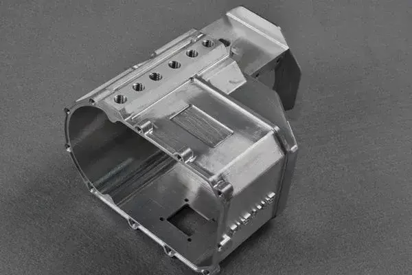
What milling gives you that other processes do not
Milling removes material with a rotating cutter, so part geometry comes from tool path and fixturing, not from a mold or a die.
Tolerance, repeatability and where the numbers come from
A CNC milling service holds dimensions by moving a cutter along a programmed path. Tolerance is therefore a function of machine geometry, tool wear, fixturing stiffness and thermal drift, not of a mold cavity. On aluminum and stainless parts we hold ±0.005 mm (±0.0002 in) on critical features when the drawing calls for it, and we measure before the part leaves the floor.
The number on a drawing matters less than which features carry it. A 200 mm long aluminum bracket with a ±0.05 mm hole spacing is a different problem from a 20 mm bushing with a ±0.005 mm bore. Tell us which dimensions are functional. If every dimension is marked tight, cost rises for features that never needed it.
Repeatability is the other half. Once a program and fixture are proven, part 2 runs like part 500. That is why milling suits bridge builds and pilot runs: you can start at one piece and scale to 10,000+ without a new tooling investment.
- 1Tight featuresBores, pockets and datums held to ±0.005 mm where the drawing requires it
- 2Proven setupProgram and fixture stay fixed across the run, so part-to-part spread stays small
- 3InspectionRaw material check, in-process monitoring and 100% inspection before shipment
Undercuts, deep pockets and why 5-axis changes the quote
A 3-axis mill reaches one face at a time. Every new face means a new setup, a new fixture and a new chance to lose datum alignment. A 5-axis machining center tilts the tool or the table, so a contoured surface, an angled port or a part with features on five sides can be cut in one or two setups.
Setup count shows up in two places: cost and tolerance stack-up. Each re-fixture adds locating error, and on a complex part that error compounds. Cutting more faces per setup keeps datums intact and usually shortens the schedule. For parts with compound angles or sculpted surfaces, 5-axis is often cheaper than the 3-axis alternative, not more expensive.
We run 16 simultaneous 5-axis machining centers, 12 four-axis mills, 27 three-axis machines and 16 mill-turn centers across 127 machines. That mix matters for quoting: a simple plate should not occupy a 5-axis spindle, and a blisk-style part should not be split across five 3-axis setups.
- 1One-setup complex partsCompound angles and contoured surfaces cut without re-fixturing
- 2Right machine for the job3-axis for prismatic plates, 5-axis for sculpted or multi-face geometry
- 3Mill-turnShafts and housings with turned and milled features in one setup
Which machine fits your part
Use this to sanity-check your geometry before requesting a quote.
| Part type | Machine | Why |
|---|---|---|
| Flat plate, holes on one face | 3-axis | Lowest cost, fast setup, no rotary motion needed |
| Part with features on 4 sides | 4-axis | Rotary table indexes between faces, fewer setups |
| Compound angles, contoured surfaces | 5-axis | Tool tilt reaches the surface without re-fixturing |
| Shaft with milled flats and grooves | Mill-turn | Turning and milling complete in one setup |
| Long part, up to 4,000 mm | Large-travel mill | 4,000 × 400 × 150 mm travel envelope |
| Compact detail part | Compact mill | 500 × 500 × 450 mm or 500 × 310 × 200 mm travel |
Material choice drives tool wear, finish and lead time
Aluminum 6061 and 7075 cut fast and hold tight tolerances well. 7075 is stronger but more abrasive on tooling, so deep pockets cost a little more. Stainless 303 machines cleanly; 304 and 316L work-harden if the cutter dwells, so feed and speed have to be right from the first pass. 17-4PH holds strength after heat treatment and is common in medical and aerospace work.
Titanium TC4 (Ti-6Al-4V) and Inconel sit at the other end. They conduct heat poorly, so the cutter edge runs hot and tool life drops. Cycle times are longer and the quote reflects that. Magnesium AZ31B and AZ91D cut easily but need chip control, since fine magnesium chips are a fire risk.
Plastics behave differently again. POM and PEEK hold dimensions; ABS and PP move with temperature and clamp pressure. Carbon fiber eats cutting tools and needs dust extraction. If your part is plastic and flat, milling may still win on tolerance; if it is a hollow shell, another process may be cheaper.
- 1Fast and stable6061, 6061-T6, 2024, 5052, 5083, 6063, 6082
- 2Harder alloys303, 304, 316L, 420, 440C, 17-4PH, 4130, 4140, 4340
- 3Difficult cutsTC4 titanium, Inconel, magnesium AZ31B / AZ91D — longer cycle times
- 4PlasticsABS, PC, PMMA, POM, PA, PEEK, PP, HDPE, carbon fiber
Surface finish and post-processing in the same supply chain
As-machined surfaces land around Ra 1.6–3.2 μm. A finer pass gets Ra 0.8–1.6 μm, and Ra 0.2–0.8 μm is possible where the geometry allows a small step-over with a sharp cutter. Very fine finishes on deep cavities are limited by tool reach, not by machine capability.
Finishing usually decides how a part is judged. Anodizing in clear, color, hardcoat or conductive grades; electroless nickel, zinc, silver and gold plating; powder coating and black oxide; bead blasting, tumbling, brushing and polishing. Laser marking is available down to 1.5 mm character height.
Keeping machining and finishing under one roof removes a common failure point. When the anodizer and the machinist are different companies, a masking error or a scratched surface becomes a schedule problem that neither side owns.
- 1As machinedRa 1.6–3.2 μm, standard cutter marks
- 2Fine finishRa 0.8–1.6 μm with a finishing pass
- 3Mirror-levelRa 0.2–0.8 μm where tool reach allows
- 4MarkingLaser engraving, minimum character height 1.5 mm
When a CNC milling service is the wrong choice
Milling is subtractive. If your part is a thin-walled enclosure with uniform 1.5 mm walls in a 200 mm box, machining it from solid means removing most of the block and fighting wall deflection. Sheet metal fabrication or die casting will be cheaper at volume.
If the part is a hollow shell with internal channels you cannot reach with a cutter, milling alone cannot make it. Tool access sets the limit. A pocket deeper than about four times the cutter diameter needs a smaller cutter, which means slower feed and more tool breakage risk.
Volume is the other factor. Milling has no tooling cost, so it wins from one piece up to a few thousand. Past that, a casting or molding tool may amortize. We quote from one prototype to 10,000+ part runs with no minimum order quantity, and the DFM review inside the quote will say when another process fits better.
- 1Thin uniform wallsSheet metal or casting beats milling from solid
- 2Unreachable internal channelsNeeds a different process or a split design
- 3High volume, simple shapeTooling-based processes amortize better
- 4Deep narrow pocketsSmall cutter, slower feed, higher risk
Milling versus other processes by part profile
| Part profile | Best fit | Note |
|---|---|---|
| Prototype bracket, 5 pieces | CNC milling | No tooling cost, drawing changes are cheap |
| Complex housing, 500 pieces | CNC milling | Setup already proven, tolerance repeatable |
| Uniform thin-wall enclosure | Sheet metal | Machining from solid wastes material |
| Simple part, 50,000 pieces | Die casting | Tooling amortizes over the volume |
| Shaft with flats and threads | Mill-turn | One setup, no second-op alignment error |
Questions engineers ask before sending an RFQ
What tolerance can a CNC milling service hold on my part?
We hold ±0.005 mm (±0.0002 in) on critical features. Whether that is achievable on your part depends on size, geometry, material and how many setups are needed. Long thin parts and deep pockets are harder than compact ones.
Send the drawing and mark the functional dimensions. The DFM analysis that comes back with the quote will say which tolerances are realistic and which ones are driving the price.
How do I know if my part needs 5-axis or 3-axis milling?
Count the faces that carry features. Holes and pockets on one face suit a 3-axis machine. Features on four sides fit a 4-axis with a rotary table. Compound angles, contoured surfaces or features on five sides point to 5-axis.
5-axis is not automatically more expensive. On a complex part it often replaces three or four 3-axis setups, and each setup you remove also removes a locating error.
What is the largest part you can mill?
Our large-travel machines cover 4,000 × 400 × 150 mm, so a 4,000 mm maximum processing size is possible. Medium machines run 750 × 1,150 × 550 mm and 600 × 600 × 600 mm. Compact machines cover 500 × 500 × 450 mm and 500 × 310 × 200 mm.
If your part sits near the edge of an envelope, mention it in the RFQ. Fixture and clamping take space that does not appear in the nominal size.
Can you machine a single prototype and then scale up?
Yes. There is no minimum order quantity, and we quote from one prototype to 10,000+ part runs. The program and fixture from the prototype carry into the production run, so the transition is mostly a scheduling step.
Production can start within 24 hours of an approved order, and parts typically ship in 3–5 days depending on material and finishing.
How are drawings and CAD files handled?
Uploads are secure and confidential. A non-disclosure agreement is available on request if your program requires one. We hold ISO 27001:2022 for information security, alongside ISO 9001:2015, IATF 16949:2016 and ISO 13485:2016.
Inspection reports are available on request. Every part is checked before shipment, covering raw material, in-process dimensions and final inspection.
What happens if my design is better suited to another process?
The DFM analysis will say so. If a part is a uniform thin-wall enclosure or a simple high-volume shape, we will point to sheet metal fabrication, die casting or vacuum casting instead of milling.
Deciding against milling on one part does not end the conversation. Several of our customers run milled prototypes and cast production parts through the same account.
Send your drawing, get a DFM review with the quote
Upload a STEP file and we will return a quotation plus a free DFM analysis within 12 hours, with a note on tolerance, material and whether milling is the right process for the part.
12-hour quoteFree DFM analysis±0.005 mmNo MOQ









