
CNC Milling and Turning: The Basics
Two subtractive processes do most of the work in a machine shop. This guide explains how each one cuts, which part shapes suit it, and where the practical limits sit. Written for design engineers and buyers who need to choose a process before sending a drawing out for quote.
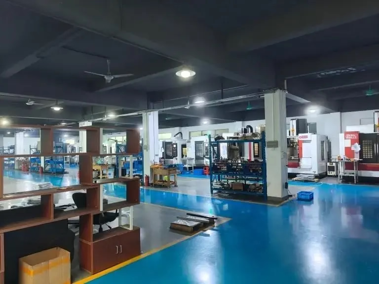
How CNC Milling Removes Metal
Milling spins a multi-tooth cutter and moves it through the workpiece. The part stays clamped to a table or vise. Each tooth takes a small chip on every pass, so material comes off as a series of overlapping cuts. A 12 mm carbide end mill running at 8,000 rpm and a feed of 2,400 mm/min will clear aluminum quickly and leave a clean floor if the stepover is kept around 40 percent of the cutter diameter.
The geometry you can produce depends on how many axes move at once. A three-axis mill handles pockets, slots, flats, and drilled holes on one or two faces. A four-axis mill adds a rotary table, so the part can index between faces without being unclamped. A five-axis center tilts both the tool and the table, which lets a short, stiff cutter reach angled walls and deep cavities in a single setup.
Fewer setups matter more than most people expect. Every time a part leaves the fixture, it picks up a new datum error. Holding a wall position to ±0.005 mm across four operations is hard. Doing the same features in one five-axis cycle is routine. That is the real argument for five-axis work on complex parts, not the ability to cut curved surfaces.
Milling leaves tool marks, and the direction of those marks follows the tool path. A 10 mm cutter with a 0.5 mm stepover will leave visible scallops on a curved surface. A 6 mm cutter with a 0.2 mm stepover cuts slower but leaves a surface that may not need hand polishing. Choose the cutter size from the smallest internal corner radius in the part, then work backward to the finish pass.
- 1Best forPrismatic parts, pockets, slots, angled faces, thin ribs
- 2Typical limitInternal corner radius must be at least the cutter radius
- 3Watch forTool deflection on deep cavities with a long reach
- 4Fixture costRises with part count per setup and with irregular shapes
How CNC Turning Removes Metal
Turning flips the motion. The workpiece spins in a chuck or between centers, and a single-point insert feeds along the axis or across the face. The cut is continuous rather than interrupted, so the load on the tool stays steady. That is why turning cuts deep and fast. A 80 mm diameter 6061 shaft can run at 2,000 rpm with a 2 mm depth of cut and a 0.25 mm/rev feed without chatter.
The natural output of a lathe is a body of revolution: shafts, bushings, pins, spacers, threaded studs, and hydraulic fittings. Diameters hold tight because the tool position relative to the spindle centerline is what sets the size. On a lathe with a good spindle, a ±0.005 mm diameter tolerance and Ra 0.8–1.6 μm finish on a bearing journal are normal production results, not special work.
Turning reaches its limit when the part needs features that are not round. Cross-drilled holes, milled flats, and keyways used to mean a second operation on a mill. Mill-turn centers changed that. A mill-turn machine holds the part in a spindle that can index and lock, then brings live tooling in from the turret. One machine, one setup, round and prismatic features in the same cycle.
Long, slender parts are the classic turning problem. A shaft with a length-to-diameter ratio above 6:1 will push away from the tool and cut a tapered profile. A steady rest, a tailstock, or a change in the cutting strategy fixes it. If a drawing calls for a 12 mm diameter over 200 mm unsupported, expect to pay for the extra setup or to accept a slower cycle.
Threads, grooves, and chamfers come almost free on a lathe. A single threading insert cuts a full profile in a few passes. Cutting the same thread with a mill is slower and needs a specific cutter. If a part is mostly round with one thread, turning wins on cycle time alone.
- 1Best forShafts, bushings, fittings, threaded parts, round flanges
- 2Typical limitLength-to-diameter ratio above 6:1 needs support
- 3Watch forChuck jaw marks on finished diameters
- 4Cost driverBar stock size and the number of tools in the turret
Milling or Turning: How to Decide
Start with the shape of the part, not the tolerance. If the dominant features are coaxial and round, turning is faster and cheaper. If the part is a block with pockets on several faces, milling is the only sensible route. Most real parts sit in between, and the question becomes how many features can be done in the first setup before the part has to move.
Count the setups. A part that needs three milling operations and one turning operation has four chances to lose position. If the same part fits in a mill-turn center, the count drops to one or two. On tight-tolerance work, setup count often drives cost more than metal removal time. This is where a shop with 16 mill-turn centers can quote differently from one with only three-axis mills.
Material guides the decision too. Aluminum and brass cut freely on both machine types. Titanium and Inconel change the picture. These alloys conduct heat poorly and work-harden at the cut, so the tool has to stay in the cut and take a real chip. Turning handles that well because the load is continuous. Milling these alloys with a small stepover and a slow feed generates heat in one spot and dulls the cutter fast.
Thin walls punish both processes, but in different ways. Milling a 0.8 mm wall on a pocket tends to lift the wall as the cutter passes. Turning a thin tubular section lets the wall deflect under the insert. Both are cuttable with light passes and support, but neither is a place to demand a tight tolerance without a conversation about how the part is held.
There is no universal winner. A shop that offers both will usually quote the cheaper route and tell you why. If a drawing can be made either way, ask for both cycle times. The answer is often not obvious from the drawing alone.
- 1Pick turningCoaxial round features, threads, grooves, high volume bar work
- 2Pick millingPrismatic shapes, pockets on multiple faces, sharp internal corners
- 3Pick mill-turnRound body with off-axis holes or flats that must stay in tolerance
What G-Code Tells the Machine
Both processes run on the same control language. G-code is a list of positions, feeds, and speeds. A line like G01 X50.0 Y25.0 F800 tells the control to move in a straight line to that point at 800 mm/min. The machine does not know what the part is. It only knows where the tool should be at each moment.
The CAM programmer decides the strategy. For milling, that means choosing the cutter, the stepdown, the stepover, and the order of operations. For turning, it means choosing the insert geometry, the depth of cut per pass, and the spindle speed. A roughing pass that is too light will rub instead of cut and wear the tool. A finishing pass that is too heavy will leave chatter marks.
Tool paths also decide where the part holds its tolerance. A pocket cut with a continuous spiral path keeps a steadier load than one cut with a zigzag path and sharp direction changes. On a long finishing pass, a constant-engagement path can cut cycle time while improving the finish. These choices are made in CAM, not at the machine.
Once a program is proven, it becomes a fixed asset. The same G-code, the same fixture, and the same tool list will produce the same part run after run. That repeatability is what makes CNC work suitable for production volumes. First-article inspection confirms the setup, and then the process runs on its own.
- 1Speeds and feedsSet by material, cutter material, and radial engagement
- 2Tool listEvery extra tool adds a tool change and a chance for error
- 3First articleConfirms the program before the run continues
Material and Finish Effects on the Cut
Material choice changes the whole calculation. Aluminum 6061-T6 and 7075 machine well on both processes and hold tight tolerances with the right cutter. Stainless 303 turns beautifully and mills acceptably. Stainless 316 and 17-4PH work-harden and need a heavier feed to get under the hardened layer. Titanium TC4 and Inconel demand rigid setups, sharp tooling, and low surface speed.
Copper and brass are soft and gummy. A sharp cutter with a high rake angle clears them, but the chips can weld to the tool edge and tear the finish. Beryllium copper needs care with dust control. Magnesium AZ31B and AZ91D cut fast and light, but the chips are a fire risk, so chip evacuation has to be planned.
Plastics behave differently again. POM and ABS cut cleanly. PEEK needs a sharp tool and a fast feed to avoid melting. Carbon fibre is abrasive, so tool life is short and the edge quality depends on the tool coating. A shop that runs these materials daily has the tooling already on the shelf, which shortens the learning curve on a new part.
Finishing options land on top of the machined surface. Anodizing adds a thin oxide layer and can shift a tight dimension by a few micrometres, so masking or a pre-plate size adjustment may be needed. Electroless nickel and zinc plating add thickness too. Bead blasting hides tool marks but rounds sharp edges. Laser marking needs at least 1.5 mm character height to stay legible after plating.
- 1Hard alloysHeavier feed, lower speed, rigid setup, sharp inserts
- 2Soft alloysHigh rake, good chip evacuation, watch for built-up edge
- 3PlatingAdds thickness; call out critical dimensions before finish
- 4BlastingCosmetic gain, but it dulls sharp edges
Where the Limits Actually Show Up
Drawings describe an ideal part. Machines produce a real one. The gap between the two usually comes from deflection, thermal growth, and fixturing. A cutter pushed hard in a deep pocket will bend and cut a wall that leans. A spindle that has run for six hours will hold a slightly different size than one that just started. Neither shows up in the drawing.
Tolerance stacking is the other quiet problem. If a part has a ±0.05 mm bore, a ±0.05 mm shaft, and a ±0.05 mm housing face, the assembly can still fail. Each feature passes inspection on its own. Only the stack fails. Designers who think in stacks save everyone a round of rework.
Inspection catches what the process drifts away from. A first article confirms the setup. In-process checks catch drift on long runs. Final inspection confirms the shipment. A shop that measures at all three stages sees a problem before the customer does. That is how a 99.99% qualification rate is held rather than hoped for.
The best time to raise a tolerance concern is before the first cut. A short note on the drawing about which dimensions are functional and which are reference lets the programmer choose the right strategy. It also lets the shop quote the part honestly instead of padding the price for risk it does not need to carry.
- 1DeflectionShows up on deep pockets, long tools, thin walls
- 2Thermal driftGrows through a shift; in-process checks catch it
- 3Stack-upCheck the assembly, not just each feature
CNC Milling and Turning Compared
Practical differences that show up on a quote sheet.
| Factor | CNC Milling | CNC Turning | Mill-Turn |
|---|---|---|---|
| Work motion | Tool rotates, part fixed | Part rotates, tool fixed | Both can rotate |
| Best shape | Blocks, pockets, ribs | Shafts, bushings, fittings | Round body plus flats |
| Typical tolerance | ±0.005 mm | ±0.005 mm on diameters | ±0.005 mm across features |
| Surface finish | Ra 0.8–1.6 μm | Ra 0.2–0.8 μm on journals | Either, depending on tool |
| Setup count | Rises with faces | Low for round parts | Usually one or two |
| Corner limit | Cutter radius | Not applicable | Live tool radius |
| Off-axis holes | Easy | Needs a second op | Built in |
| Best for | Complex prismatic parts | High-volume round parts | Tight-tolerance hybrids |
The Short Answer
If the part is mostly round, turn it. If it is mostly prismatic, mill it. If it has both and the tolerances are tight, use a mill-turn center and keep it in one setup. When the drawing is ambiguous, ask for both cycle times before you commit.
Common Questions
Can a part be both milled and turned?
Yes, and most complex parts are. The question is whether both operations happen in one setup or several. A mill-turn center does both without unclamping the part, which removes datum shift between operations.
If the part is simple, two separate operations on a mill and a lathe can be cheaper. The trade-off is setup time and the risk of position error when the part moves.
What tolerance can CNC milling and turning hold?
On a rigid setup with the right tooling, ±0.005 mm is achievable on both processes. That is not a default, though. It depends on the feature, the material, and how the part is held.
A deep pocket with a long tool will not hold that. Neither will a thin wall without support. If a dimension needs ±0.005 mm, mark it on the drawing so the programmer can plan for it.
Which process gives a better surface finish?
Turning generally produces a lower Ra on round surfaces because the cut is continuous. A bearing journal at Ra 0.2–0.8 μm is normal on a good lathe.
Milling leaves a scalloped pattern set by the stepover. A small stepover and a sharp cutter can reach Ra 0.8–1.6 μm, but the tool marks still follow the path.
Why does setup count raise the price so much?
Each setup needs a fixture, a proving run, and a first-article check. It also adds a chance for the part to shift and lose position relative to the previous operation.
Reducing four setups to two often cuts more cost than shaving cycle time. This is why mill-turn centers quote well on parts with features on several faces.
How does material choice change the quote?
Aluminum cuts fast and tool wear is low. Stainless and titanium cut slower, wear tools faster, and need more rigid setups. That shows up as a higher hourly rate or a longer cycle, or both.
Plastics cut quickly but need specific tooling and chip control. A shop that already runs your material will quote it more accurately than one that has to learn it.
Do you offer both processes under one roof?
Yes. We run 5-axis, 4-axis, and 3-axis mills plus mill-turn centers in the same plant, so a part can move between processes without leaving the building.
Uploads are kept confidential and an NDA is available on request. A quotation and free DFM analysis come back within 12 hours.
Send the Drawing, Get a Straight Answer
Tell us the material, the tolerance, and the quantity. We will tell you which process fits and why, with a quote and a free DFM review within 12 hours.
12-hour quote100% inspectionNo minimum orderNDA on request
More from the Shop Floor
We publish setup notes, tooling trials and inspection data from the factory floor.











