
How Is the Turning Milling Combination Achieved?
A mill-turn center does not turn and mill at the same time. It hands the part from a turning spindle to a milling spindle inside one setup, with one work coordinate system. This guide shows the five setup steps we use on 16 mill-turn centers, the parameters that matter, and the parts where the combination is the wrong choice.
In this article
- 1
- 2
- 3
- 4
- 5
- 6
- 7
- 8
Key takeaways
What makes a turning milling combination achieved
A conventional lathe spins the part and pushes a single-point tool along X and Z. A conventional mill holds the part still and spins the tool. A mill-turn center has both spindles and both tool systems on one bed, and the control runs both sets of cycles under one program number. That is the whole idea behind a turning milling combination achieved in a single setup.
The machine is built around a turning spindle with a C-axis. When the C-axis indexes to a commanded angle and locks, the spindle stops acting like a lathe and starts acting like a rotary table. Live tooling in the turret or on a B-axis head then cuts the cross holes, flats, and slots that would normally wait for a second machine.
The second half of the combination is the sub-spindle. It picks up the part on the back side, so the same program can machine both ends without an operator flipping the workpiece. One setup, one datum, one inspection sheet.
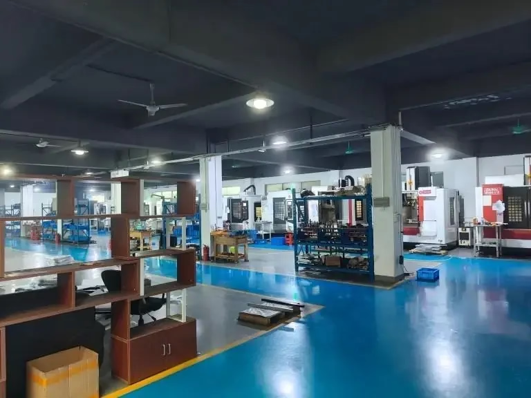
We run 16 mill-turn centers at GreatLight, alongside 16 simultaneous 5-axis machining centers and 27 three-axis machines. On the right parts, mill-turn removes a handling step and a re-fixturing error source at the same time.
Which parts belong on a mill-turn center
Start with the part geometry. If the outside diameter is turned and there are features that are not parallel to the turning axis, the part is a candidate. Cross holes at 90 degrees, hex flats, milled wrench pads, keyways, and radial slots all qualify. Hydraulic fittings, motor housings, sensor bodies, and medical instrument handles are typical.
Size sets the ceiling. Our mill-turn centers handle a Ø400 mm rotary table, and the largest turning envelope we quote on these machines is 4,000 mm in length with a 4,000 × 400 × 150 mm travel on the large platform. Parts that exceed the sub-spindle chuck grip, or that need a steady rest, move to a different machine plan.
Quantity matters as much as shape. For one or two pieces, a lathe plus a 3-axis mill can be faster because the programming is simpler. Above roughly 50 pieces, the mill-turn setup time pays back quickly. Between those two numbers, we compare both routes in the DFM report and quote the cheaper one.
Tolerance is the last filter. Mill-turn holds ±0.005 mm on turned diameters and the same on milled features when the same datum is used. If a drawing calls for a bore-to-flat position of ±0.002 mm, the operation may still need a finish pass on a jig grinder or a dedicated boring setup.
- 1Good fitTurned body with cross holes, flats, or slots at an angle to the axis.
- 2Good fitBatches from 50 to 10,000+ pieces where handling time dominates.
- 3Poor fitShafts longer than 6:1 length-to-diameter without a steady rest.
- 4Poor fitParts needing a feature on a face that the sub-spindle cannot reach.
Machine configurations that make it possible
The simplest configuration is a 3-axis lathe with a C-axis and live tooling in the turret. It can drill and mill on the part centerline and at indexed angles. It cannot tilt the tool, so angled holes need a secondary setup or a different machine.
A 4-axis mill-turn adds a Y-axis to the turret. Now the live tool can move off center, which means cross holes can be drilled without interpolating the C-axis. Cycle times drop and tool life improves because the drill enters perpendicular to the surface.
A 5-axis mill-turn adds a B-axis head that tilts the spindle. This is the configuration that handles true compound angles, undercut features, and contoured pockets on a turned body. GreatLight runs these alongside 12 four-axis mills and 16 five-axis centers, so parts can be routed by feature rather than by habit.
Bar feeders and sub-spindles change the economics again. A bar-fed mill-turn center can run unattended for hours, cutting the part off, machining the back side, and dropping it into a catcher. That is where the combination becomes a production method rather than a convenience.
Tool holders, coolant, and chip evacuation
A mill-turn center runs live tooling in a turret or on a B-axis head, and the holders are smaller than what a machining center accepts. ER16 and ER20 collets, plus small Capto or HSK-A32 interfaces, are common. Rigidity drops with size, so take lighter radial cuts and more axial passes on long-reach tools.
Coolant strategy changes when the tool spins inside a turning envelope. High-pressure through-tool coolant at 30–70 bar clears chips from deep cross holes. In aluminium, chip welding on the drill margin is the most common failure, and it usually traces back to low pressure or a worn collet.
Chip evacuation is harder on a mill-turn than on a lathe because the part is not always spinning away from the cut. Program a peck or a dwell so the chips break, and use the sub-spindle air blow before the transfer. A chip trapped between the chuck jaws adds runout that no offset can fix.
Thermal drift matters on long unattended runs. Our spindles are monitored, and we re-check critical diameters every 20–30 parts. On a 0.005 mm tolerance, a 2 °C shift in the shop can move a bore by a measurable amount.
Where the combination stops working
The sub-spindle cannot reach every face. A feature on the side of a flange that faces away from both chucks needs a different approach, usually a 5-axis operation after the mill-turn work. We flag this in DFM rather than discovering it at the inspection bench.
Long slender parts are the other failure case. Once the length-to-diameter ratio passes about 6:1, the part deflects under cutting force, and the milled feature drifts away from the turned axis. A steady rest can extend the range, but it also blocks tool access.
Material hardness sets a practical limit for live tooling. Inconel and hardened tool steel can be milled on a mill-turn center, but the small holders and low torque limit depth of cut. On those jobs, turning on the lathe and milling on a 5-axis center is often the faster route even with two setups.
Finally, the tolerance stack has to be honest. A mill-turn center holds ±0.005 mm when the same work offset is used throughout. If the drawing requires a feature relationship tighter than that, plan a finishing operation instead of pushing the mill-turn beyond its capability.
5 setup steps to get the combination running
- 11. Define one work coordinate systemTouch off the turning spindle face and the sub-spindle face to a common Z zero. Set G54 for the main spindle and G55 for the sub-spindle, with the Z offset measured, not calculated. Error here shows up as an eccentric step at the handover, usually 0.02–0.05 mm.
- 22. Prove the handover before cuttingDry-run the transfer with the part clamped in the main chuck only. Close the sub-spindle chuck at 1.5–2.5 MPa, confirm the grip, then release the main chuck. Check runout with a dial indicator; keep it under 0.01 mm TIR before committing to a cut.
- 33. Set the live tool offsetsMeasure every live tool on the presetter and load the values with the tool radius and length. For a B-axis head, verify the pivot distance and the tool tip offset in the control, then cut an air pass to confirm the commanded angle matches the physical angle within 0.01°.
- 44. Split turning and milling speedsTurning passes for aluminium 6061 run 250–400 m/min surface speed at 0.1–0.25 mm/rev feed. Live milling on the same part runs 3,000–8,000 rpm with 0.02–0.05 mm/tooth. Stainless 316 drops to 120–180 m/min turning and 1,500–3,000 rpm milling. Never reuse the turning feed for a milling cycle.
- 55. Inspect at the handover, not only at the endMeasure the concentricity between a turned diameter and a milled feature right after the first completed part. If the runout is drifting, re-check the chuck pressure and the sub-spindle Z offset before running the rest of the batch.
Mill-turn vs separate turning and milling
Use this table when deciding how to route a round part with off-axis features.
| Criterion | Mill-turn center | Lathe plus mill |
|---|---|---|
| Batch size | 50 to 10,000+ pieces | 1 to 50 pieces |
| Setups per part | One | Two or more |
| Datum changes | None | One per machine |
| Position tolerance | ±0.005 mm typical | ±0.01 mm or looser |
| Cycle time per part | Lower at volume | Lower at one-off |
| Programming effort | Higher, one program | Lower, two programs |
| Chip control | Harder | Simpler |
| Best for | Turned body with cross features | Prototype or long shafts |
When to choose mill-turn
Choose a mill-turn center when a turned body carries cross holes, flats, or slots and the batch is above roughly 50 pieces. Stay with a lathe plus a mill for prototypes, one-offs, and shafts longer than 6:1 length-to-diameter.
Frequently asked questions
Can a mill-turn center cut the part off and finish the back side in the same cycle?
Yes, if the machine has a sub-spindle and a bar feeder. The main spindle turns the front, the sub-spindle takes the part, the tool cuts it off, and the program continues on the back face.
The limit is the sub-spindle chuck grip and the length of the part. Very long parts need a steady rest or a different machine plan.
What tolerance can a turning milling combination hold?
On our mill-turn centers we hold ±0.005 mm on turned and milled features that share one work coordinate system. Surface finish runs Ra 0.8–1.6 μm as a standard milled finish, and Ra 0.2–0.8 μm when a finishing pass is programmed.
Tighter relationships between two features usually need a separate finishing operation.
Is mill-turn cheaper than two separate operations?
Above roughly 50 pieces, usually yes, because one setup removes a handling step and a re-fixturing error source. Below that, two simple setups on a lathe and a 3-axis mill can be faster to program and run.
We quote both routes in the DFM report and let the numbers decide.
Which materials run well on a mill-turn center?
Aluminium 6061 and 7075, stainless 303 and 316L, brass C36000, and titanium TC4 all run on our mill-turn centers with the right speeds. Copper and beryllium copper need slower milling speeds because they work-harden.
Hardened tool steel above 45 HRC is possible but slow, and we usually move it to a 5-axis center.
How do you check concentricity after the spindle handover?
We indicate a turned diameter and a milled feature on the first completed part, then re-check every 20–30 parts on a long run. Raw material is inspected on receipt, and 100% inspection happens before shipment.
Inspection reports are available on request.
Send a drawing, get a mill-turn plan
We review the geometry, propose the routing, and return a quotation with free DFM analysis within 12 hours. Production can start within 24 hours, and parts ship in 3–5 days.
12-hour quote100% inspectionNo minimum order quantityNDA on request
More CNC machining notes
We publish setup notes, tooling trials and inspection data from the factory floor.











