
Raspberry Pi Aluminum Alloy Case: Design and Machining Basics
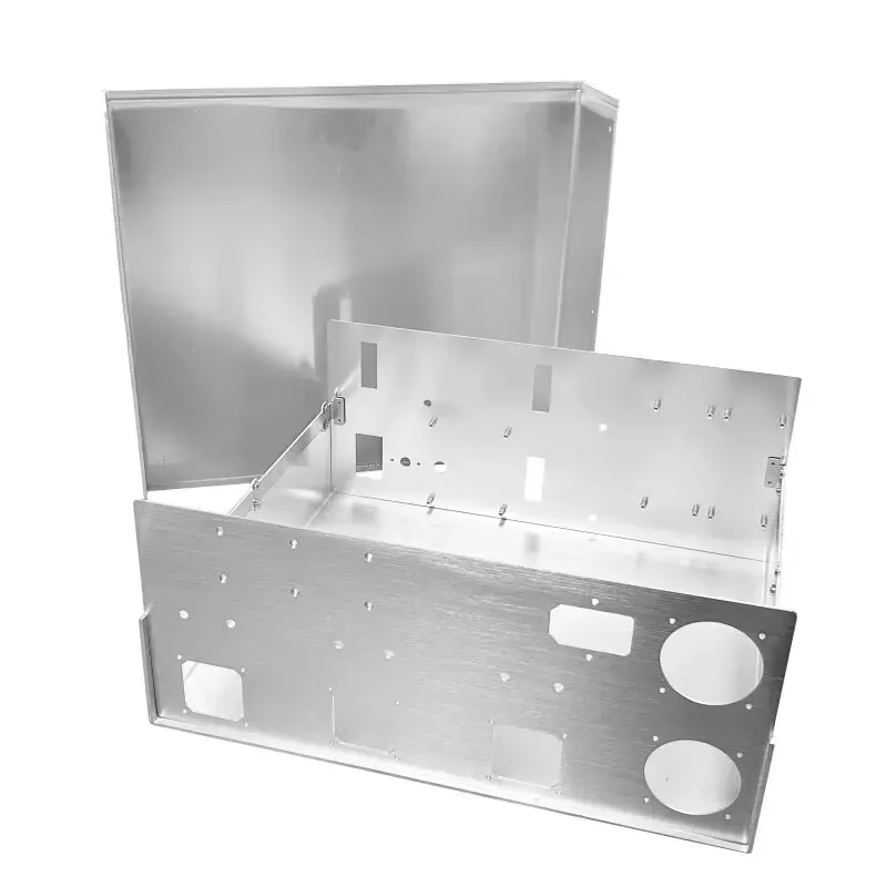
This page covers what a Raspberry Pi aluminum alloy case has to get right: board fit, port alignment, heat path and finish. It is written for hardware engineers and buyers who need a milled or die-cast enclosure that survives field use, not a display shelf. After reading, you can pick a process, set tolerances and spot the mistakes that cause returns.
In this article
- 1
- 2
- 3
- 4
- 5
- 6
- 7
- 8
Key takeaways
What a Raspberry Pi aluminum alloy case actually has to do
A Raspberry Pi aluminum alloy case is not a cosmetic shell. It holds a 85 × 56 mm board in a fixed position, keeps every connector reachable, and pulls heat out of a chip that can run near 80 °C under load. Get any of those wrong and the enclosure becomes the problem.
The board itself has two mounting holes on a 58 × 49 mm pattern, and the port cluster sits on two edges. Any enclosure has to respect that geometry. Aluminum gives you stiffness at 1.5–3 mm wall thickness, which plastic cannot match without ribs and extra volume.
We machine these enclosures in 6061-T6 or cast them in ADC12. Both take anodizing well. The choice usually comes down to quantity and how much post-machining the port openings need.
- 1Board fitClearance around the PCB edge, typically 0.3–0.5 mm per side.
- 2Standoff heightEnough for the tallest bottom-side component plus solder joint.
- 3Port accessCutouts aligned to the connector centerline, not the board outline.
Wall thickness, standoffs and the tolerance stack
Start with the stack, not the drawing. Board thickness on a Raspberry Pi 4 is about 1.6 mm, and the mounting holes are plated. A standoff that is 0.1 mm short lets the board flex when you tighten a screw. A standoff that is 0.1 mm tall leaves the port cluster sitting high in its cutout.
For machined enclosures we hold standoff height at ±0.05 mm and hole position at ±0.05 mm. That leaves room in the stack for board variation, screw seating and coating thickness. If the case gets anodized, add 10–25 μm per surface to your clearance numbers.
A common mistake is designing the lid clearance from the top of the tallest connector. The microSD card and the camera ribbon cable both sit outside that envelope. Measure the real assembly, or leave 1.5 mm of headroom and a slot for the ribbon.
- 1Standoff height±0.05 mm on machined parts.
- 2Hole position±0.05 mm relative to the enclosure datum.
- 3Coating allowanceAdd 10–25 μm per anodized surface.
- 4Headroom1.5 mm above the tallest connector or cable.
How the case moves heat away from the SoC
An aluminum case works as a heat spreader when there is a real path from the chip to the metal. Air gaps kill that path. A thermal pad of 1.0–1.5 mm, compressed about 30 %, gives contact without stressing the board.
Wall thickness matters less than contact area. A 2 mm floor directly under the SoC outperforms a 4 mm wall on the far side of the case. If the enclosure has a lid, tie the lid to the body with a machined lip or a screw boss so heat has somewhere to go.
Vent slots help, but they mostly move air across the board. They do not replace a conduction path. On a passively cooled unit running at 60–70 % load, a metal case with a pad typically holds 10–15 °C lower than the same board in a sealed plastic box.
- 1Thermal pad1.0–1.5 mm thick, compressed about 30 %.
- 2Contact areaAt least the full footprint of the SoC package.
- 3Lid couplingMachined lip or screw boss, not a loose snap fit.
Port cutouts, screw bosses and assembly
Port cutouts are where most enclosures look cheap. USB, Ethernet and HDMI connectors sit at slightly different heights, and the openings need to clear the plastic overmold on a cable, not just the metal shell. Add 0.5–1.0 mm around the connector body.
We hold cutout position at ±0.10 mm against the mounting datum. That is tight enough that a standard cable seats without scraping, and loose enough to keep the part economical. Chamfer the inside edge 0.3–0.5 mm so the connector does not catch.
Screw bosses need enough thread depth. For M2.5 in aluminum, 4–5 mm of engagement is safe. For M3, 5–6 mm. Do not run a screw into a 1.5 mm wall without a boss; the thread will strip on the second assembly.
If the case is opened often, use threaded inserts or a captured nut. They cost more per unit but survive repeated service far better than tapped aluminum.
- 1Cutout clearance0.5–1.0 mm around the connector body.
- 2M2.5 engagement4–5 mm of thread depth in aluminum.
- 3Edge chamfer0.3–0.5 mm on the inside face.
- 4Service accessThreaded inserts if the lid comes off often.
Surface finish and what it costs you
Anodizing is the default for these enclosures. Clear anodize keeps the machined look, and hardcoat adds wear resistance on the edges. Both add thickness, so mask the standoffs and any grounding contact if you need electrical continuity.
Powder coating gives more color options and hides tool marks. It also adds 60–100 μm, which is enough to close a tight port cutout. If the design has 0.5 mm clearance, powder coat is fine. If it has 0.2 mm, use anodize.
Bead blasting before anodizing produces a matte, even surface. Brushing leaves visible lines and shows handling marks sooner. For a case that sits on a desk, bead blast plus clear anodize is the low-risk choice.
- 1Clear anodizeKeeps the machined look, adds 10–25 μm.
- 2HardcoatBetter edge wear, mask grounding points.
- 3Powder coatAdds 60–100 μm; check cutout clearance.
- 4Bead blastEven matte surface before anodizing.
CNC, die casting or sheet metal: which one fits
CNC is the right answer for prototypes and low volume. A milled 6061-T6 case gives you ±0.005 mm on critical features, no tooling cost, and changes are a program edit. Lead time for a first article is short because there is no mold to cut.
Die casting takes over when volume justifies the tool. ADC12 flows well into thin walls, and the per-part cost drops. The trade-off is draft angle, parting lines and a small amount of post-machining on the port openings and screw bosses.
Sheet metal works for flat, folded enclosures where the board sits on a tray. It is cheap at volume but harder to make rigid without extra bends. For a Raspberry Pi case with tight port alignment, CNC or die casting usually wins.
- 1CNC1 to 500 units, no tooling, tight tolerance.
- 2Die castingAbove 5,000 units, lower part cost.
- 3Sheet metalFlat tray designs, cheap at volume.
Enclosure process comparison
Numbers reflect our standard capability, not a guarantee for every geometry.
| Process | Best volume | Tolerance | Watch out for |
|---|---|---|---|
| CNC 6061-T6 | 1–500 units | ±0.005 mm | Tool access inside deep pockets |
| Die casting ADC12 | 5,000+ units | ±0.10 mm plus machining | Draft angle and parting lines |
| Sheet metal | 500–5,000 units | ±0.10 mm | Rigidity without extra bends |
| CNC 7075 | 1–200 units | ±0.005 mm | Anodize color shifts between lots |
| CNC plus hardcoat | 1–500 units | ±0.005 mm | Masking for grounding points |
Which route to take
For prototypes and anything under 500 units, machine the case from 6061-T6 and anodize it. For a product shipping in thousands, move to die casting and machine only the port cutouts and screw bosses. If your port clearance is under 0.3 mm, stay with CNC or switch from powder coat to anodize.
Common questions
What wall thickness should a Raspberry Pi aluminum alloy case use?
For a machined case, 1.5–3 mm on the walls and floor is enough for stiffness and heat spreading. Going below 1.5 mm makes the part chatter during milling and flex when the board is screwed down.
If the case has large unsupported panels, add a boss or a step instead of thickening the whole wall. That keeps weight and cost down.
Does an aluminum case really lower the SoC temperature?
Yes, if there is a conduction path. A thermal pad of 1.0–1.5 mm compressed about 30 % against the SoC and a metal floor gives the heat somewhere to go. Without the pad, the case acts mostly as a shield.
Vent slots help with air movement but do not replace contact. On a passively cooled board at moderate load, the pad plus metal case is the bigger factor.
How much clearance do the port cutouts need?
Leave 0.5–1.0 mm around the connector body, not just the metal shell. Cable overmolds are larger than the connector and are what usually rubs.
Hold cutout position at ±0.10 mm to the mounting datum, and chamfer the inside edge 0.3–0.5 mm so cables slide in without catching.
Can I anodize the case after machining?
Yes. Clear and hardcoat anodize are common on 6061-T6 and ADC12. Mask the standoffs and any grounding contact if you need electrical continuity through the case.
Anodize adds 10–25 μm per surface. Add that to your clearance budget before you release the drawing.
What is the smallest order you accept?
We have no minimum order quantity. One prototype and a 10,000-part run both go through the same process. For prototypes, CNC is usually the fastest route because there is no tooling.
Quotation and a free DFM analysis come back within 12 hours. Production can start within 24 hours after that.
Which aluminum grade is best for this enclosure?
6061-T6 is the standard choice for machined enclosures. It machines cleanly, takes anodize evenly and holds ±0.005 mm on critical features.
7075 is stiffer and stronger but costs more and can show color variation after anodizing. ADC12 is the die-casting grade when volume takes over.
Send your enclosure drawing
Upload a STEP file and we will return a quotation and a DFM analysis within 12 hours. Uploads stay confidential, and an NDA is available on request.
12-hour quote100% inspection±0.005 mm toleranceNo minimum order quantity
More from the shop floor
We publish setup notes, tooling trials and inspection data from the factory floor.











