
Introduction to DFROBOT Aluminum Alloy Shell
What the DFROBOT aluminum alloy shell actually is, which alloys it uses, how it is machined, and where the design limits sit. Written for engineers and buyers who need to judge whether this enclosure approach fits their own product.
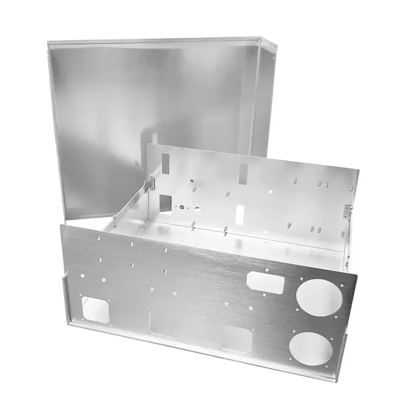
What a DFROBOT Aluminum Alloy Shell Is
A DFROBOT aluminum alloy shell is a machined enclosure for electronics, usually built around 6061-T6 or 6063 extrusion stock. It does not get its properties from a coating. It gets them from the alloy, the temper, and the wall thickness a machinist can hold without the part moving.
The shell does three jobs at once. It carries the board, it spreads heat away from the power stage, and it keeps dust and fingers out of the terminals. Those jobs pull in different directions. A thin wall saves weight but flexes during clamping. A thick wall holds threads but adds mass and cost.
Most shells we see are 100 mm to 300 mm long, with wall thickness between 1.5 mm and 4 mm. Below 1.2 mm the part starts to chatter on a three-axis mill unless you support it from the inside. Above 5 mm you are usually paying for metal that carries no load.
The material is not exotic. What matters is consistency. A 6061-T6 block with certified chemistry behaves the same on Monday and on Friday. Recycled or unmarked stock does not, and that is where tolerance drift starts.
- 1Typical alloys6061-T6 for structural shells, 6063 for extruded profiles, 7075 when stiffness matters more than weldability.
- 2Typical wall range1.5 mm to 4 mm covers most electronics enclosures without chatter or wasted mass.
- 3Heat pathThe shell itself is the heatsink when the board is fastened directly to the base.
Why 6061-T6 Is the Default for This Shell
6061-T6 is the workhorse for enclosure work. It machines cleanly, takes anodizing evenly, and holds a thread without a helicoil in most sizes. Yield strength sits near 276 MPa, which is enough for a handheld device and most rack hardware.
6063 is the extrusion grade. If your shell starts as a profile and only needs end milling, 6063 gives a better surface finish straight off the die and anodizes to a brighter clear coat. It is softer, so do not use it for threads that will be opened and closed often.
7075 is the stiff option. It is roughly twice the cost of 6061 and slower to machine, but it holds thin ribs that 6061 would bend. Aerospace and drone frames use it for that reason. For a bench power supply shell, 7075 is wasted money.
2024 and 5052 show up in sheet-metal versions of the same product family. 5052 bends well and resists salt spray. 2024 is stronger but needs careful corrosion protection because of its copper content.
- 16061-T6Default for machined shells. Good finish, good threads, moderate cost.
- 26063Best for extruded profiles with light secondary machining.
- 37075Use only where stiffness or thin ribs justify the price.
How the Shell Gets Machined
A hollow box with thin walls is one of the harder shapes to hold. The first operation is usually the outside profile, clamped on a sacrificial block. The second operation opens the pocket, and that is where wall deflection shows up.
On a three-axis machine, a deep pocket with a 2 mm wall will spring inward under cutter pressure. Rough it with a larger tool, leave 0.3 mm to 0.5 mm of stock, then finish with light passes. A 6 mm end mill at 0.2 mm radial engagement leaves a wall that stays where the drawing says.
Five-axis machining helps when the shell has angled faces or ports on multiple sides. Fixturing the part once and reaching all faces reduces the number of setups and the cumulative position error between them. Our shop runs 16 simultaneous five-axis centers for exactly this kind of work.
Tolerance is not the hard part. Repeatability is. A shell that measures ±0.005 mm on the first article still has to measure that on part 500, which is why in-process checks matter more than a single final inspection.
- 1Roughing stockLeave 0.3 mm to 0.5 mm on thin walls before the finishing pass.
- 2Thin-wall ruleKeep radial engagement low and cutter overhang short when the wall is under 2 mm.
- 3Setup countFewer setups means less stacked position error across faces.
Surface Finish and Anodizing Behavior
Anodizing does not hide machining marks. It amplifies them. A wall left at Ra 1.6–3.2 μm will show tool paths and any chatter once it comes out of the dye tank. If the shell is a visible product face, plan for Ra 0.8–1.6 μm before anodizing, and Ra 0.2–0.8 μm if it is a decorative bezel.
Hardcoat anodizing adds roughly half the coating thickness into the part. A 25 μm hardcoat grows about 12 μm outward and 13 μm inward on a 6061 surface. Threads and bores that must stay on size need masking or a pre-plate allowance.
Clear anodizing on 6061 shows the alloy's natural gray. On 6063 it reads brighter. If two halves of the same enclosure come from different alloys, they will not match after anodizing, even with the same dye lot.
Bead blasting before anodizing gives a uniform matte that hides small scratches from handling. Brushing gives a directional grain. Both change the surface by a few micrometres, which matters if the shell has a sealing face.
- 1Visible facesMachine to Ra 0.8–1.6 μm before anodizing to avoid visible tool marks.
- 2Hardcoat growthBudget about 25 μm of coating and mask critical bores and threads.
- 3Alloy matchingKeep both halves of a shell on the same alloy or the anodized color will differ.
Where the Shell Design Starts to Fight Back
Sharp internal corners are the most common problem. An end mill leaves a radius equal to its own, so a 6 mm cutter cannot produce a 0.5 mm internal corner. Either accept the radius or add a relief slot, which is cheaper than a second operation with a smaller tool.
Very thin floors under a connector cutout will bow when the connector is tightened. A 1 mm floor under an M12 connector is not enough. Go to 2.5 mm or add a local boss. The boss costs less than a cracked shell in the field.
Long, narrow shells over 400 mm tend to twist after machining as internal stress releases. Stress-relieved stock and symmetric material removal reduce the movement. If the part still moves, a light finish pass after a rest period pulls it back.
Screw bosses need wall thickness around them. A rule that works: boss outer diameter at least twice the screw diameter, with at least 1.5 mm of wall around the boss. Below that, the boss splits when the screw is driven.
- 1Internal cornersMatch the corner radius to the smallest cutter you are willing to run.
- 2Thin floorsKeep at least 2.5 mm under load-bearing connectors.
- 3Long partsUse stress-relieved stock above roughly 400 mm length.
Machined Shell vs Sheet Metal vs Die Casting
Pick the process before you finalize the drawing. The tooling cost and the wall you can hold change the whole design.
| Factor | CNC machined shell | Sheet metal shell | Die cast shell |
|---|---|---|---|
| Best quantity | 1 to 10,000+ | 50 to 5,000 | 5,000 and up |
| Tooling cost | None | Low to medium | High |
| Minimum wall | 1.5 mm typical | 0.8 mm typical | 2.0 mm typical |
| Tolerance | ±0.005 mm | ±0.1 mm | ±0.05 mm |
| Surface finish | Ra 0.8–1.6 μm | Ra 1.6–3.2 μm | Ra 1.6–3.2 μm |
| Internal features | Bosses, threads, pockets | Bends and rivets only | Draft-limited ribs |
| Change cost | Edit the program | New bend layout | New die |
When to Machine the Shell and When Not To
If you need internal bosses, tight tolerance, or fewer than 5,000 pieces, machine the shell from 6061-T6. If the part is a flat cover with no internal features and you need thousands of units, sheet metal will cost less per piece. Die casting only wins once the volume absorbs the tooling.
Questions Engineers Ask About This Shell
Can the DFROBOT aluminum alloy shell be anodized in a specific color?
Yes. Clear, color, hardcoat, and conductive anodizing are all available. Color matching is done against a physical sample or a Pantone reference, not a screen.
Note that dye uptake varies slightly with alloy and surface texture. If two parts of one assembly come from different alloys, expect a small color difference even in the same bath.
What is the smallest wall thickness you can machine reliably?
Around 1.2 mm on a supported wall with light finishing passes. Below that, chatter and deflection become hard to control on a three-axis machine.
If the design needs a thinner wall, move the feature to a five-axis setup or add a temporary support rib that gets removed in a later operation.
Does the shell need a separate heatsink?
Often no. When the PCB is fastened directly to the base with thermal pads, the shell becomes the heatsink. The limiting factor is the thermal path from the component to the aluminum, not the aluminum itself.
If the heat load is above roughly 20 W in a sealed shell, add external fins or a forced-air path. Machined fins on a 6061 shell are straightforward to produce.
How do you keep the shell flat after machining?
Start with stress-relieved stock, remove material symmetrically, and rough and finish in separate operations. On long parts, a rest period between roughing and finishing lets internal stress release before the final cut.
For a 300 mm shell we typically hold flatness within 0.05 mm across the base. Tighter than that usually needs a fixture that matches the final mounting points.
What surface finish should I specify for a visible shell?
Ra 0.8–1.6 μm is the practical target for an anodized visible face. It removes visible tool marks without adding much cycle time.
Ra 0.2–0.8 μm is for decorative or sealing surfaces. It costs more because it needs slower finishing passes and often a finer cutter.
Can you start production before I finalize the cosmetic details?
Yes, for the functional geometry. We quote and run a free DFM analysis within 12 hours, and production can start within 24 hours on approved geometry.
Cosmetic changes such as blasting media or anodizing color can be settled in parallel, since they do not change the machining program.
Send the Drawing and Get a DFM Review
Upload your shell model and we will return a quotation with a free DFM analysis within 12 hours. No minimum order quantity, from one prototype to a 10,000-piece run.
12-hour quoteFree DFM analysis100% inspectionNDA on request
More Machining Notes
We publish setup notes, tooling trials and inspection data from the factory floor.











