
Aluminum Alloy Shell DFROBOT2: How the Housing Is Built
A close look at the aluminum alloy shell DFROBOT2 / B+ enclosure: which alloy suits a robot controller housing, how wall thickness and tolerances are set, and where machining stops making sense. Written for mechanical engineers and sourcing teams who need to judge a housing design before it goes to tooling.
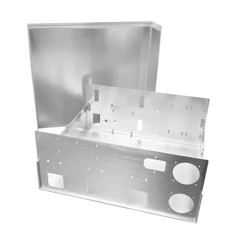
What the Aluminum Alloy Shell DFROBOT2 Has to Do
The aluminum alloy shell DFROBOT2 / B+ is the outer housing of a mobile robot controller. Its job is not decoration. It carries the board, spreads heat away from the driver stages, and survives being bumped while the robot moves. Every feature on the part exists because one of those three jobs needed it.
Start with the heat path. Power transistors dump waste heat into a small area of the PCB. If that heat has nowhere to go, junction temperature climbs and the driver derates. An aluminum housing fixes this by giving the heat a low-resistance route: die to copper pad to thermal interface material to a machined boss on the shell.
The second job is mechanical. A robot controller gets dropped, kicked, and pressed against fixtures. The shell has to hold its shape so the PCB inside does not flex. That is why the mounting bosses and the lid flange are the stiffest sections of the part.
The third job is electromagnetic. A continuous metal enclosure acts as a shield if the lid makes good contact with the body along the whole perimeter. Gaps break that shield. So the flange flatness matters as much as the wall thickness.
- 1HeatSpread driver losses into the housing mass
- 2StructureKeep the PCB flat under shock loads
- 3ShieldingContinuous metal path between lid and body
Why 6061-T6 Suits This Shell
Most robot housings in this size class are cut from 6061-T6. The alloy machines cleanly, holds a thread, and takes anodizing without blotching. Yield strength sits around 276 MPa, which is far more than a hand-sized enclosure needs.
2024 machines better and is stronger, but it corrodes faster and anodizes to a darker, less even finish. For an outdoor robot, that is a problem. For a lab unit that never sees rain, 2024 is a reasonable upgrade if weight is tight.
7075 is the strongest common aluminum, but it costs more and welds poorly. If the shell is a single machined part with no welded joints, 7075 works. If you plan to weld a lid frame onto the body, stay with 6061.
ADC12 is the die-casting grade. It flows well into thin walls and is cheap at volume, but it is brittle compared with wrought alloys and porosity can appear near thick bosses. Treat it as a volume option, not a prototype option.
- 16061-T6Default choice for machined housings
- 22024Stronger, weaker corrosion resistance
- 37075Highest strength, poor weldability
- 4ADC12Casting grade, better above 5,000 parts
Wall Thickness, Ribs, and Bosses
For a machined shell in the 100–200 mm range, a 2.5–3.0 mm wall is the usual starting point. Thinner walls save mass but start to deflect when the operator squeezes the housing. Thicker walls cost cycle time and add nothing structural.
Inside the shell, ribs do more work than extra wall thickness. A 3 mm rib running between two bosses raises stiffness far more than adding 1 mm to the whole wall. Put ribs where the PCB is longest unsupported.
Bosses need a minimum wall around a threaded hole. For an M3 thread in aluminum, keep at least 3 mm of material around the hole. For M4, use 4 mm. Below that, the boss can split when the screw is torqued.
Corners are the other trap. Sharp internal corners concentrate stress and are hard to reach with a small end mill. A 2 mm internal radius lets a 4 mm cutter clean the corner in one pass and removes the stress riser at the same time.
- 1Wall2.5–3.0 mm for 100–200 mm shells
- 2Ribs3 mm ribs beat thicker walls
- 3Bosses3 mm around M3, 4 mm around M4
- 4Corners2 mm internal radius minimum
Machining Sequence and Setup Choices
A shell like this usually runs in two or three setups. The first op cuts the outside profile, the top face, and the main pocket. The second op flips the part to finish the flange face and the mounting holes. If the part has angled connectors or side ports, a 5-axis setup removes the extra fixture.
Holding the part is the hard part. Thin walls move when a vise clamps them. Soft jaws bored to the profile, or a vacuum fixture on a flat face, keep the wall from collapsing during the cut. We check wall thickness after each op on thin sections.
Roughing removes most of the stock with a larger cutter. Finishing follows with a smaller tool and lighter passes. On a 3 mm wall, a 0.3 mm finishing pass keeps cutting force low enough that the wall does not spring back after the clamp releases.
Deburring is not optional on a housing that people handle. A 0.3–0.5 mm chamfer on every external edge removes the burr and prevents the anodized coating from flaking at sharp corners.
- 1Setup countTwo setups typical, three with side ports
- 2WorkholdingSoft jaws or vacuum, never bare vise on thin walls
- 3Finishing pass0.3 mm on 3 mm walls
- 4Edges0.3–0.5 mm chamfer before anodizing
Which Tolerances Actually Matter
Not every dimension on a housing needs the same tolerance. Tightening all of them raises cost and slows inspection without improving function. Pick the ones that touch another part.
The most important is the flange face. If the lid sits on a flange that is not flat, the seal gap varies and the shield breaks. Keep flange flatness inside 0.05 mm across the full length.
Boss height and hole position come next. The PCB mounts on those bosses, so their height controls how the connectors line up with the panel cutouts. ±0.05 mm on boss height is a normal target.
Overall length and width can drift more, usually ±0.1 mm, because nothing else references them. Datum selection drives this: pick the PCB mounting face as the primary datum and dimension everything from there.
- 1Flange flatness0.05 mm across the full length
- 2Boss height±0.05 mm
- 3Overall size±0.1 mm is usually enough
- 4DatumPCB mounting face as primary datum
Machined Shell vs Die-Cast Shell
Compare the two routes before you commit to tooling.
| Factor | Machined 6061-T6 | Die-cast ADC12 | When it matters |
|---|---|---|---|
| Tooling cost | None | High upfront cost | Below 5,000 parts, machining wins |
| Wall thickness | 2.5–3.0 mm stable | 1.5–2.0 mm possible | Thin walls need casting |
| Tolerance | ±0.005 mm achievable | ±0.1 mm typical | Mating faces need machining |
| Porosity | Not an issue | Possible near thick bosses | Sealed enclosures care |
| Finish | Anodizes evenly | Needs more prep | Visible housings care |
| Lead time | Parts ship in 3–5 days | Weeks after tooling | Prototypes favor machining |
| Weight | Slightly heavier | Lighter at equal stiffness | Mobile robots care |
Which Route to Pick
For prototypes and runs under a few thousand parts, machine the aluminum alloy shell DFROBOT2 from 6061-T6 and anodize it. Switch to die casting only when volume is high enough to absorb tooling cost and you can tolerate ±0.1 mm on non-critical faces, then machine the flange and bosses back to tolerance.
Questions Engineers Ask
Does the shell need hardcoat anodizing?
Only if the housing sees abrasion or repeated handling. Standard clear anodizing at 10–15 μm protects against corrosion and keeps the surface looking even.
Hardcoat reaches 25–50 μm and is much harder, but it builds up on threads and tight bores. Mask those features or cut the thread after coating.
Can the lid and body be welded instead of screwed?
Yes, but then the electronics must survive the heat. TIG welding 6061 pulls a lot of heat into the part, and the shield becomes permanent, so you cannot open the unit for repair.
For a serviceable controller, screws along the flange are the safer choice. Use a screw every 30–40 mm to keep the shield continuous.
What surface finish should I call out?
Ra 1.6–3.2 μm on internal faces is fine because nobody sees them. For a visible outer surface that will be anodized, ask for Ra 0.8–1.6 μm so the coating looks uniform.
Going finer than Ra 0.8 μm on a housing rarely shows after anodizing and adds polishing cost.
How do I stop thin walls from warping during machining?
Rough the part, let it rest, then finish. Stress built up in the plate releases when material is removed, and the part moves. A rest period between roughing and finishing lets that movement happen before the final cut.
Light finishing passes and soft-jaw workholding do the rest.
Is a gasket needed between the lid and body?
For indoor use with no liquid exposure, a machined flange with 0.05 mm flatness is usually enough. Add a gasket when the robot works near coolant, dust, or washdown.
A gasket adds about 0.5–1.0 mm to the stack, so account for it in the boss height.
What should I send for a quote?
Send a STEP file, a 2D drawing with the tolerances that matter, the alloy, and the finish. Note which faces are cosmetic.
That is enough for a DFM review and a quote within 12 hours.
Send the Housing Model for Review
We machine aluminum housings from one prototype to 10,000+ part runs, with a DFM report and quote back within 12 hours.
12-hour quote±0.005 mm100% inspectionNo minimum order
More From the Shop Floor
We publish setup notes, tooling trials and inspection data from the factory floor.











