
Is CNC Machining and Milling the Same Thing?
They are not. CNC machining describes how a machine is controlled; milling describes one way a rotating tool cuts metal. This page explains the boundary between the two terms, which operations sit under each one, and how to read a drawing or a quote without mixing them up.
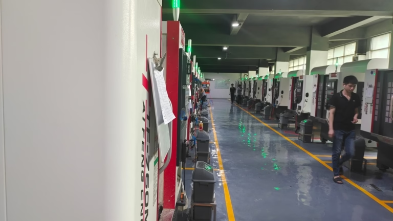
CNC Machining Is the Control Layer, Milling Is One Operation
The confusion starts because the two words live at different levels. CNC stands for computer numerical control. It describes a machine that reads a program of coordinates and moves its axes to those coordinates without an operator turning handwheels. The same control layer runs a lathe, a mill, a wire EDM, a punch press or a laser. So when someone asks whether cnc machining and milling are the same thing, the honest answer is that one is the parent category and the other is a child of it.
Milling is a specific cutting operation. A multi-tooth rotary cutter spins on a spindle and is fed sideways into the workpiece. Each tooth takes a small chip. Because the tool can move along X, Y and Z at the same time, milling produces flat faces, slots, pockets, profiles and 3D contoured surfaces. The cutter stays round; the shape comes from the path.
A CNC lathe works the other way around. The workpiece spins and a single-point tool feeds along its length. A mill-turn center does both: it turns an OD, then switches to a milling spindle to cut flats, cross holes and keyways on the same part without a second setup. That single machine can therefore perform CNC turning and CNC milling in one program.
Practical consequence: if a drawing says "CNC machined", it tells you the part was cut under numerical control. It does not tell you whether the material was removed by a spinning tool, a spinning workpiece or a wire. If a drawing says "milled", it does tell you the surface was generated by a rotating cutter, and that constrains the geometry you can ask for.
- 1CNC machiningAn umbrella term for computer-controlled subtractive processes.
- 2CNC millingOne of those processes: rotating cutter, moving workpiece or tool.
- 3CNC turningWorkpiece rotates; single-point tool removes material.
- 4Mill-turnBoth operations in one machine, often one setup.
What Actually Falls Under CNC Machining
It helps to list the operations a job shop groups under the CNC umbrella. Milling, turning, drilling, boring, reaming, tapping, thread milling, and wire or sinker EDM all sit there. So do grinding centers and some punch and laser cells. They share the control architecture, not the cutting mechanics.
Face milling, peripheral milling and end milling are the three names you will see most often on a milling routing. Face milling uses the bottom or side of a wide cutter to flatten a top surface. Peripheral milling cuts along the side of the cutter, which is how you generate a square shoulder. End milling uses the end teeth to plunge, slot and profile. A Ø12 mm carbide end mill in aluminium might run at 8,000–12,000 rpm with a 0.05–0.15 mm tooth feed; the same cutter in 17-4PH stainless drops to roughly 1,200–2,000 rpm.
Drilling is often filed under milling because it happens on the same machine with the same spindle, but it is a different cut. A drill removes material only at its tip and cannot correct the position error it starts with. If a hole needs a true position tighter than ±0.05 mm, the proven sequence is spot drill, drill undersize, then bore or ream. Chat with an engineer before you assume a drilled hole will hold a press-fit tolerance.
Turning belongs to the same family but not to milling. A turned part is round by definition. The moment you need a hex, a slot or an off-axis hole, the part either moves to a mill or the job goes to a mill-turn center. This is the single most common reason a quote comes back with an extra operation listed.
- 1On a millFace, peripheral, end milling, drilling, boring, tapping.
- 2On a latheTurning, facing, grooving, threading, parting.
- 3On EDMHardened steel, sharp internal corners, thin walls.
- 4On a mill-turnRound body plus milled features in one setup.
How the Difference Shows Up in Part Geometry
Milling reaches what a turning tool cannot. A square pocket with a 3 mm inside radius needs a cutter of that radius, which means a small tool, lower feed and more time. A sharp internal corner at 90° cannot be milled at all with a round cutter; it needs EDM or a relief cut. Designers who know this add a corner radius and save real money.
Deep pockets follow a similar rule. The usable depth of a small end mill is roughly 3–5 times its diameter before deflection and chip evacuation become the limit. A 6 mm cutter is comfortable to about 18–30 mm deep. Beyond that, step down to a smaller cutter or switch to EDM. This is a geometry limit, not a machine limit.
Turning handles round features far faster. A Ø50 mm aluminium shaft with a simple profile turns in a fraction of the time a mill would need to interpolate the same shape. On a part with a 20:1 length-to-diameter ratio, though, turning deflection becomes the problem and a steady rest or a different process may be needed.
Wall thickness is the last boundary worth naming. Thin walls below about 0.5 mm in aluminium and 1 mm in stainless will move under clamping and cutting force. You can still make the part, but plan on light finishing passes, soft jaws and possibly a stress-relief step between roughing and finishing.
- 1Round and axialTurning is faster and cheaper.
- 2Prismatic and contouredMilling, usually 3-axis or 5-axis.
- 3Sharp internal cornerEDM, or add a radius.
- 4Deep narrow pocketSplit the tool, or change process.
Setup Count, Tolerance and Surface Finish
Every time a part moves to a new machine or a new fixture, error stacks up. A 3-axis mill needs one setup per face it must reach. A part with features on five sides might take three or four setups, which multiplies the chance of a datum shift. A simultaneous 5-axis center can reach those features in one setup with the tool tilted, so the relationship between faces stays tight.
Tolerance is usually driven by the process, not by the control system. We hold ±0.005 mm (±0.0002 in) on critical features when the geometry allows it, and we say so when it does not. A deep bore in a thin-wall part will not repeat at that level no matter which machine cuts it. On turned parts, diameter is easy to control; length across a shoulder is harder because it depends on the tool setting.
Surface finish maps the same way. As-machined surfaces land around Ra 1.6–3.2 μm. A planned finishing pass at a small stepover reaches Ra 0.8–1.6 μm. Below that, Ra 0.2–0.8 μm usually means a dedicated finishing operation, a smaller tool or a secondary process such as fine grinding or polishing.
The takeaway is simple. Choosing milling or turning changes the geometry you can hold and the number of setups. Choosing a finish spec changes the time and tooling. Both belong in the same conversation at the quoting stage.
- 13-axisOne setup per accessible face.
- 25-axisComplex geometry in one setup.
- 3Mill-turnRound and prismatic features together.
- 4Finishing passControls Ra more than the base process does.
CNC Machining vs Milling: Side by Side
Scope, motion and typical output for each term.
| Item | CNC machining | CNC milling |
|---|---|---|
| Scope | Umbrella term for controlled cutting | One operation inside that umbrella |
| Motion | Depends on the machine | Rotating cutter, moving axes |
| Typical machines | Lathes, mills, EDM, grinders | 3-axis, 4-axis, 5-axis mills |
| Best geometry | Anything machinable | Prismatic, pockets, contours |
| Round parts | Turning is the usual choice | Possible, but slower |
| Tolerance | Set by process and geometry | ±0.005 mm on good features |
| Surface finish | Ra 1.6–3.2 μm as machined | Ra 0.8–1.6 μm with a finish pass |
| Setup count | Varies by process | One per face on 3-axis |
Which Word Should Be on Your Drawing?
Use CNC machining when you mean the general process and are not specifying how material is removed. Use milling when the geometry is prismatic and a rotating cutter is the right tool. Use turning or mill-turn when the part is largely round. If you are unsure, send the model and we will tell you which operation fits before you commit.
Frequently Asked Questions
Can a CNC machine only mill?
No. The control system is process-agnostic. The same CNC architecture runs lathes, mills, EDM, grinders and punch presses. What changes is the mechanical structure: a mill holds the workpiece and spins the tool, a lathe spins the workpiece and feeds a stationary tool.
Is turning a type of CNC machining?
Yes. Turning is a CNC machining operation, but it is not milling. The workpiece rotates and a single-point tool removes material along its length. If your part needs flats, slots or cross holes, those features are milled, either on a second machine or on a mill-turn center in the same setup.
Why is my milled pocket limited to a 3 mm corner radius?
Because the cutter is round. The smallest inside radius a mill can produce equals the cutter radius. A 3 mm radius means a 6 mm cutter, which also sets how deep the pocket can go before deflection becomes a problem. Adding a larger radius or switching to EDM removes that limit.
Does 5-axis milling hold tighter tolerances than 3-axis?
Not automatically. 5-axis helps most when it reduces setups, because each setup adds datum error. On a part with features on five sides, one 5-axis setup usually holds face-to-face relationships better than three 3-axis setups. On a simple flat plate, 3-axis is just as accurate and cheaper.
Can milling and turning be done on one machine?
Yes, on a mill-turn center. It turns an outside diameter, then uses a milling spindle to cut flats, keyways and cross holes without releasing the part. That is useful for shafts and fittings where concentricity between the turned body and the milled feature matters.
What tolerance should I put on a milled surface?
Put the tightest tolerance only where it is functionally needed. General milled dimensions at ±0.05 mm are routine. Critical fits at ±0.005 mm are achievable on rigid parts with good geometry. Over-tolerancing the whole drawing adds inspection time and cost without improving the part.
Send the Model, Get a Process Recommendation
Upload your files and we will review the geometry, suggest milling, turning or mill-turn, and return a quotation with a free DFM analysis within 12 hours.
12-hour quote100% inspectionNDA on requestNo minimum order
More Machining Notes
We publish setup notes, tooling trials and inspection data from the factory floor.











