
Robot Piccolo Micro CNC: What It Does and Where It Stops
A plain explanation of micro CNC for engineers who build small robot parts. We cover spindle speed, tool runout, chip evacuation, tolerance stack-up, and the point where micro milling stops being the right process.
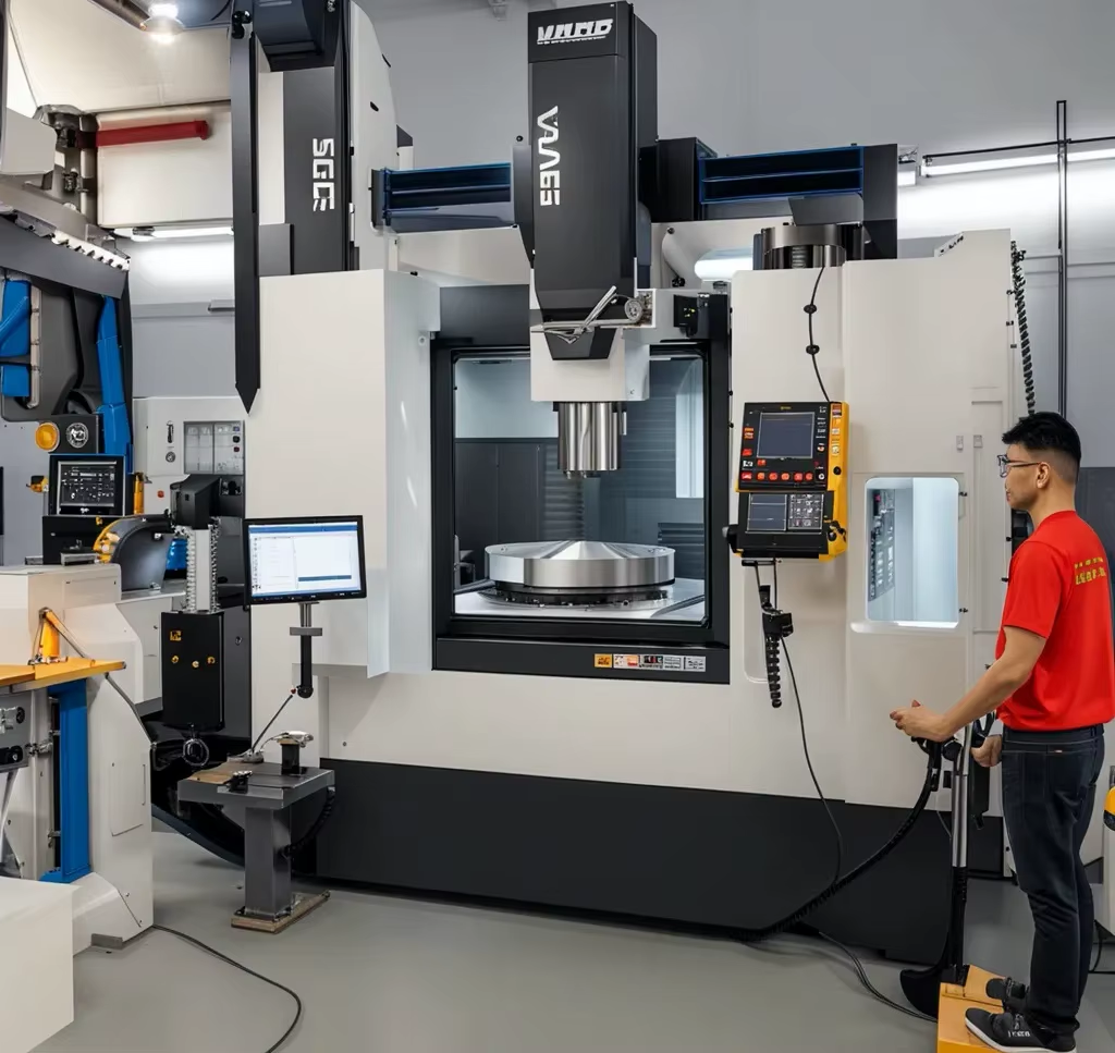
What robot piccolo micro CNC actually cuts
Robot piccolo micro CNC is a small-footprint machining setup for parts measured in millimeters, not meters. The motion system is a standard CNC platform: ballscrews, linear guides, and closed-loop control. What changes is the tool. End mills run from Ø0.2 mm to Ø3 mm, spindles turn at 40,000 rpm and above, and feed rates are measured in millimeters per minute rather than millimeters per tooth.
The name refers to the class of work, not a single machine model. Any shop that holds a Ø0.5 mm end mill in a shrink-fit holder and machines a 2 mm deep pocket is doing micro CNC, whether the machine is a dedicated micro mill or a 5-axis center with a high-speed spindle. The workpiece is usually a robot component: a harmonic drive housing, a sensor bracket, a wrist joint insert, or a gripper jaw.
The reason engineers ask about it is scale. A humanoid robot arm has dozens of small features that must fit together: bearing bores, dowel pin holes, cable channels, and thread inserts. A 0.1 mm error in one bore can shift a whole joint. Micro CNC exists to hold those features in one setup instead of three.
It is not a different physics. It is the same chip formation you learned in a machining course, pushed into a regime where tool deflection and heat become the dominant variables instead of cutting force.
- 1Typical tool rangeØ0.2 mm to Ø3 mm end mills; below Ø0.5 mm, runout matters more than spindle power.
- 2Typical part sizePockets and bores from 0.5 mm to 50 mm, on parts under 200 mm overall.
- 3Typical tolerance±0.005 mm on critical bores; ±0.02 mm on non-critical profiles.
Why small tools fail: runout, deflection, and heat
A Ø0.5 mm carbide end mill has a core diameter around 0.3 mm. Push it sideways by 0.01 mm and it snaps. That is the whole game. Tool runout at the holder is the first thing to measure, because 0.005 mm of runout means one flute does all the cutting and the other flutes just rub.
Deflection scales badly as tools shrink. Stiffness goes with the fourth power of diameter, so a tool half the size is sixteen times floppier. A 0.02 mm depth of cut that feels conservative on a Ø6 mm tool is aggressive on a Ø0.5 mm tool. This is why micro CNC feeds are often set by trial cuts, not by a formula.
Heat is the second limit. At 40,000 rpm the surface speed on a Ø1 mm tool is already 126 m/min in aluminum. Chips are tiny and carry little heat away, so most of the heat goes into the tool and the workpiece. A 0.05 mm chip can weld to the flute and take the edge with it.
Chip evacuation decides the rest. In a 2 mm wide, 6 mm deep slot, a 0.01 mm chip has nowhere to go. Air blast beats flood coolant here, because flood coolant cannot reach the bottom of a narrow slot and mist coolant leaves fines behind.
- 1Measure runout firstA dial indicator on the flute, not the shank. Above 0.005 mm, change the holder.
- 2Cut shallow0.02–0.05 mm radial depth for tools under Ø1 mm; step down rather than push sideways.
- 3Clear chipsAir blast at 6–8 bar for slots and pockets; mist only for open profiles.
Tolerance stack-up in micro robot parts
A single ±0.005 mm bore is achievable on a good machine. A joint with four stacked tolerances is a different problem. If a bearing bore, a dowel hole, a shoulder face, and a housing depth each carry ±0.005 mm, the stack can reach ±0.02 mm. That may be more than the bearing can absorb.
The fix is not always a tighter tolerance. Often it is a datum change. Machine the bearing bore and the shoulder face in the same setup so the axial relationship is set by the machine, not by two separate fixtures. This is where 5-axis work pays for itself: one setup, one datum, fewer stacked errors.
Material choice moves the number too. Aluminum 6061 and 7075 hold a bore well at room temperature but expand more than steel. A 20 mm aluminum bore grows about 0.005 mm over a 10 °C shop swing. If the part runs warm, a cold inspection number is not the number that matters.
For robot joints, we usually ask which feature sets the fit and which features are just clearance. Tighten the fit feature, open the clearance features, and let the drawing reflect that. A uniform ±0.005 mm callout on every dimension costs money and does not improve the joint.
- 1One datum per jointKeep the fit bore and its shoulder in the same setup.
- 2Split the callouts±0.005 mm on fits, ±0.05 mm on clearance and cable channels.
- 3Watch thermal driftAluminum bores move about 0.005 mm per 10 °C on a 20 mm diameter.
Fixturing and workholding for tiny parts
A vise is the wrong answer for most micro parts. Clamping force of 2 kN on a 3 mm wall will deform it before the cutter touches it. Soft jaws machined to the part profile, or a vacuum plate for flat parts, keeps the part still without crushing it.
Thin walls are the classic failure. A 0.5 mm wall in aluminum will spring back after the vise opens, so the measured dimension changes. Cut the wall in two passes with a light finish pass, or leave a sacrificial rib that gets removed in the last operation.
For parts under 20 mm, we often machine a pocket in a fixture plate and glue the blank down with cyanoacrylate. It sounds crude. It works because the glue line is uniform and there is no clamping distortion. The part is released with a solvent bath or a hot plate.
Deburring matters more at this scale. A 0.05 mm burr on a 1 mm bore is 5 percent of the diameter. Hand deburring with a scraper often beats a tumbler, because a tumbler rounds the edges you wanted sharp.
- 1Soft jaws or vacuumAvoid vise clamping on walls under 2 mm.
- 2Glue fixturingCyanoacrylate on a machined pocket for parts under 20 mm.
- 3Deburr by handA 0.05 mm burr is 5 percent of a 1 mm bore.
How we hold micro tolerances in production
Five steps from stock to inspected part.
- 1Check the blank and the datumMeasure stock size and flatness. Face the datum face first, then reference every later operation to it. A 0.02 mm flatness error on the blank becomes a 0.02 mm error in the part.
- 2Rough with a larger toolUse a Ø3 mm tool for roughing at 0.3 mm axial depth and 0.3 mm radial width. Leave 0.1 mm on walls and 0.05 mm on floors for the finishing tool.
- 3Finish with the smallest practical toolStep down 0.02–0.05 mm, feed 0.01–0.02 mm per tooth, spindle 40,000 rpm or higher. One spring pass with no radial engagement cleans the wall.
- 4Inspect in-processCheck the fit bore before the part leaves the machine. If it is out, recut it in the same setup instead of re-fixturing. We inspect 100 percent of parts before shipment.
- 5Deburr and re-measureHand deburr the edges, then re-check the dimensions that matter. Deburring can remove 0.01 mm from a sharp edge if it is done carelessly.
Micro milling vs micro turning vs EDM
Use this when the feature drives the process choice, not the part envelope.
| Feature | Micro milling | Micro turning | Wire EDM |
|---|---|---|---|
| Round bore, Ø0.5–5 mm | Good with a boring head | Best, single-point accuracy | Possible, slow, needs a start hole |
| Square pocket, 1 mm deep | Best, corner radius equals tool radius | Not practical | Good, sharp internal corners |
| Thin wall under 0.5 mm | Risky, deflection and chatter | Good on a supported tube | Best, no cutting force |
| Hardened steel above 50 HRC | Needs carbide or CBN tooling | Needs ceramic or CBN inserts | Best, cuts any hardness |
| Through slot, 0.3 mm wide | Possible, fragile tool | Not practical | Best, Ø0.25 mm wire |
| Surface finish Ra 0.2–0.8 μm | Achievable with a finish pass | Achievable with a wiper insert | Leaves a recast layer, needs post-finish |
When micro CNC is the right call
For prismatic parts with pockets, slots, and bores under 5 mm, micro milling in one 5-axis setup is the proven route. For round parts with a single dominant bore, micro turning is faster and more accurate. For walls under 0.5 mm or hardened steel above 50 HRC, wire EDM wins on both accuracy and tool life.
Questions engineers ask about micro CNC
What is the smallest tool you run, and what does it cost in cycle time?
We run carbide end mills down to Ø0.2 mm in aluminum and brass, and Ø0.3 mm in stainless and titanium. Below Ø0.5 mm, cycle time is dominated by step-down passes, not by feed rate.
A 4 mm deep, 1 mm wide slot cut with a Ø0.5 mm tool takes roughly 20 minutes of spindle time. The same slot with a Ø2 mm tool takes 4 minutes but cannot reach the corner radius.
Can you hit ±0.005 mm on a production run, not just a prototype?
Yes, on features we can reach with a finishing pass and measure in-process. The limit is usually the feature, not the machine. A deep bore with a length-to-diameter ratio above 5 is harder to hold than a shallow one.
We inspect 100 percent of parts before shipment and provide reports on request. If a feature cannot hold ±0.005 mm reliably, we tell you before cutting metal.
What materials are practical at this scale?
Aluminum 6061, 7075, and 2024 are the easiest. Brass C36000 and beryllium copper cut cleanly and hold sharp edges. Stainless 303 and 17-4PH are workable with slower feeds.
Titanium TC4 and Inconel are possible but tool life drops sharply under Ø1 mm. For those, expect more tool changes and a higher part cost.
How do you handle thin walls and small features without distortion?
We avoid vise clamping on walls under 2 mm. Soft jaws machined to the part profile, vacuum plates, or glue fixturing on a machined pocket keep the part stable without crushing it.
For walls under 0.5 mm, we leave a sacrificial rib and remove it in the last operation, or we recommend wire EDM instead.
What surface finishes can micro CNC leave?
As-machined surfaces run Ra 1.6–3.2 μm. A finishing pass with a sharp tool and light step-down reaches Ra 0.8–1.6 μm. Fine finishes down to Ra 0.2–0.8 μm are possible on flat and cylindrical faces.
Bead blasting, tumbling, and polishing are available if the drawing calls for a cosmetic finish rather than a functional one.
Do you sign an NDA for robot and humanoid programs?
Yes. Uploads are secure and confidential, and we sign an NDA on request before reviewing drawings. Our ISO 27001:2022 certification covers information security for customer data.
There is no minimum order quantity. We run from one prototype to 10,000+ part runs, and a quote with free DFM analysis comes back within 12 hours.
Send us the small parts that keep failing inspection
Upload your drawings and we will review the micro features, flag what cannot hold tolerance, and quote within 12 hours. No minimum order quantity, NDA on request.
12-hour quote100% inspection±0.005 mm toleranceNo minimum order
More micro machining notes
We publish setup notes, tooling trials and inspection data from the factory floor.











