GreatLight CNC Machining Factory logo
CNC Machining
Rapid Prototyping
Materials
Industries
News
About GL

Get Instant Quote

Surface Engineering

Shot Peening Benefits for Gears

The real gains land where gears fail: the root fillet. We machine the tooth form, control the peening variables, and verify the compressive layer before parts ship.

Root fillet peeningAlmen intensity controlGear tooth flank±0.005 mm3–5 day shippingNo MOQ
CNC Lathe Technical Specifications Terminology
2011Machining gears since
16Simultaneous 5-axis centers
99.99%Qualification rate
150Technicians on staff
Failure Modes

Where Unpeened Gears Break First

Four complaints we hear from gearbox and drivetrain engineers before peening enters the drawing.

01

Do you see pitting on the tooth flank?

A ground flank leaves a thin, lightly stressed skin. Under repeated contact the subsurface stays in tension, micropits open, and the flank spalls. Field returns then carry a gearbox teardown and a full rebuild, not a rework of one tooth.

02

Are teeth cracking at the root fillet?

The fillet is the highest-stress zone on any loaded tooth. A visible machining mark or a sharp grind line there acts as a stress riser. Cracks start in service, usually well inside the warranty window, and the fix is a new gear set rather than a repair.

03

Is the case depth doing all the work?

Carburizing and induction hardening build a hard case. That does not put the surface into compression. Two gears with the same case depth can differ by a wide margin in bending fatigue life once residual stress is measured instead of assumed.

04

Did a supplier change the peening recipe?

Shot size, coverage, and intensity often go unrecorded. The part still looks peened. The compressive layer is thinner than the drawing assumed, and the first fatigue failure arrives at 40% of expected life. No paperwork means no traceable cause.

Process Control

Peening That Matches the Drawing

We treat peening as a measured process step, not a finishing afterthought.

CNC Machining Services Online
Mechanism

How the Compressive Layer Forms

Spherical media strike the surface at controlled velocity. Each impact yields a shallow dimple and stretches the metal around it. The stretched skin wants to return, but the material beneath holds it in place, so the surface ends up in compression with a balancing tension zone below.

That compression is what resists crack initiation. Cracks open under tension, and a compressive surface closes them again on every load cycle. On a gear tooth the effect is strongest exactly where bending stress peaks, at the root fillet, and that is where we aim coverage first.

  • 1
    CoverageFull coverage at the fillet, verified by visual and Almen strip checks.
  • 2
    IntensitySet from the drawing or from a fatigue requirement you give us.
  • 3
    MediaCast steel, conditioned cut wire, glass bead, or ceramic, chosen per material.
6011
Machining First

Why We Machine Before We Peen

Peening does not remove tool marks, it buries them. We cut the tooth form, blend the root fillet to the drawing radius, and control flank finish to Ra 0.8–1.6 μm on the 5-axis centers before any media touches the part. Distortion from heat treat is corrected in a separate step, so the geometry that gets peened is the geometry you specified.

After peening we do not grind the fillet. Grinding removes the compressive layer and puts a fresh tensile skin back on the highest-stress zone. If a flank needs final sizing, it happens before peening, and the peening follows as the last mechanical operation.

  • 1
    Fillet radiusCut to drawing tolerance, no sharp grind lines left in the root.
  • 2
    Flank finishRa 0.8–1.6 μm typical, measured before peening.
  • 3
    SequenceRough, heat treat, finish machine, peen, inspect, ship.

Get Instant Quote

Selection

When Peening Helps and When It Does Not

Use this to decide whether the process belongs on your part.

ConditionDoes peening help?Reason
Bending fatigue at root filletYes, main benefitCompression opposes the peak tensile stress
Flank pitting under contact loadYes, with good finishPeening plus low Ra delays micropit growth
Already ground after peeningNo, layer removedGrinding strips the compressive skin
Sharp fillet, no radiusFix geometry firstA stress riser defeats the peening
Soft plastic or low-strength alloyRarely worth itDimples flatten without holding stress
Thin wall, tight flatnessPlan for distortionPeening can bow thin sections
Casting porosity near surfaceSometimesCloses surface pores, does not fix deep voids
Shaft or spline in same drivetrainYes, same setupSame fatigue logic applies to the shaft
Capabilities

What We Do Around the Peening Step

One shop for the geometry, the surface, and the paperwork.

01

5-Axis Gear Machining

16 simultaneous 5-axis centers cut tooth forms, helical flanks, and blended root fillets in one setup. Fewer setups means the fillet radius holds its tolerance.

02

CNC Milling and Turning

27 three-axis machines, 12 four-axis mills, and 16 mill-turn centers handle gear blanks, hubs, shafts, and splines up to 4,000 mm.

03

Surface Finishing

Bead blasting, tumbling, brushing, and polishing prepare the flank before peening and clean up after. We keep the two operations in a fixed order.

04

Rapid Prototyping

One-off gears and test coupons before you commit to a run. No minimum order quantity, from a single prototype to 10,000+ parts.

05

Inspection and Reports

Raw material check, in-process monitoring, final inspection. Dimensional and surface reports on request, with the peening parameters recorded.

06

Material Selection Support

4130, 4140, 4340, 17-4PH, and case-hardening steels behave differently under peening. We flag the grade before the process is fixed.


Scope

Process Variables We Control

The numbers a fatigue engineer usually asks for.

VariableWhat we setWhy it matters
Media typeCast steel, cut wire, glass, ceramicHardness match to part material
Media sizeSelected to fillet radiusToo large bridges the fillet
Almen intensityPer drawing or fatigue targetSets the depth of compression
Coverage100% at fillet, documentedUncovered zones stay in tension
Angle of impactNormal to fillet surfaceOblique impact wastes energy
Nozzle distanceFixed per fixtureRepeatability across the run
Fixture rotationUniform exposurePrevents streaks and shadows
Post-peen stepNo grinding on filletProtects the compressive layer
Why GreatLight

Numbers Behind the Process

Fifteen years in Dongguan, three plants, and a quality system built for drivetrain work.

15Y

Machining Since 2011

Fifteen years of gear, shaft, and housing work across automotive, aerospace, robotics, and industrial machinery programs.

±0.005

Tolerance in mm

Held on machined features, or ±0.0002 in. Fillet radii and tooth geometry are checked against the drawing before peening starts.

4,000

Millimeters Max Size

Large gear blanks and shafts fit the travel envelope. Compact work down to 500 × 310 × 200 mm runs on the smaller centers.

IATF

16949:2016 Certified

Automotive quality management alongside ISO 9001:2015, ISO 13485:2016 for medical, and ISO 27001:2022 for data security.

12H

Quote Turnaround

Quotation and free DFM analysis within 12 hours. Production can start within 24 hours of approval, with parts shipping in 3–5 days.

99.99%

Qualification Rate

100% inspection before shipment on every order, with reports available. Historical late-delivery probability stays below 2%.

Applications

Where These Gears Go

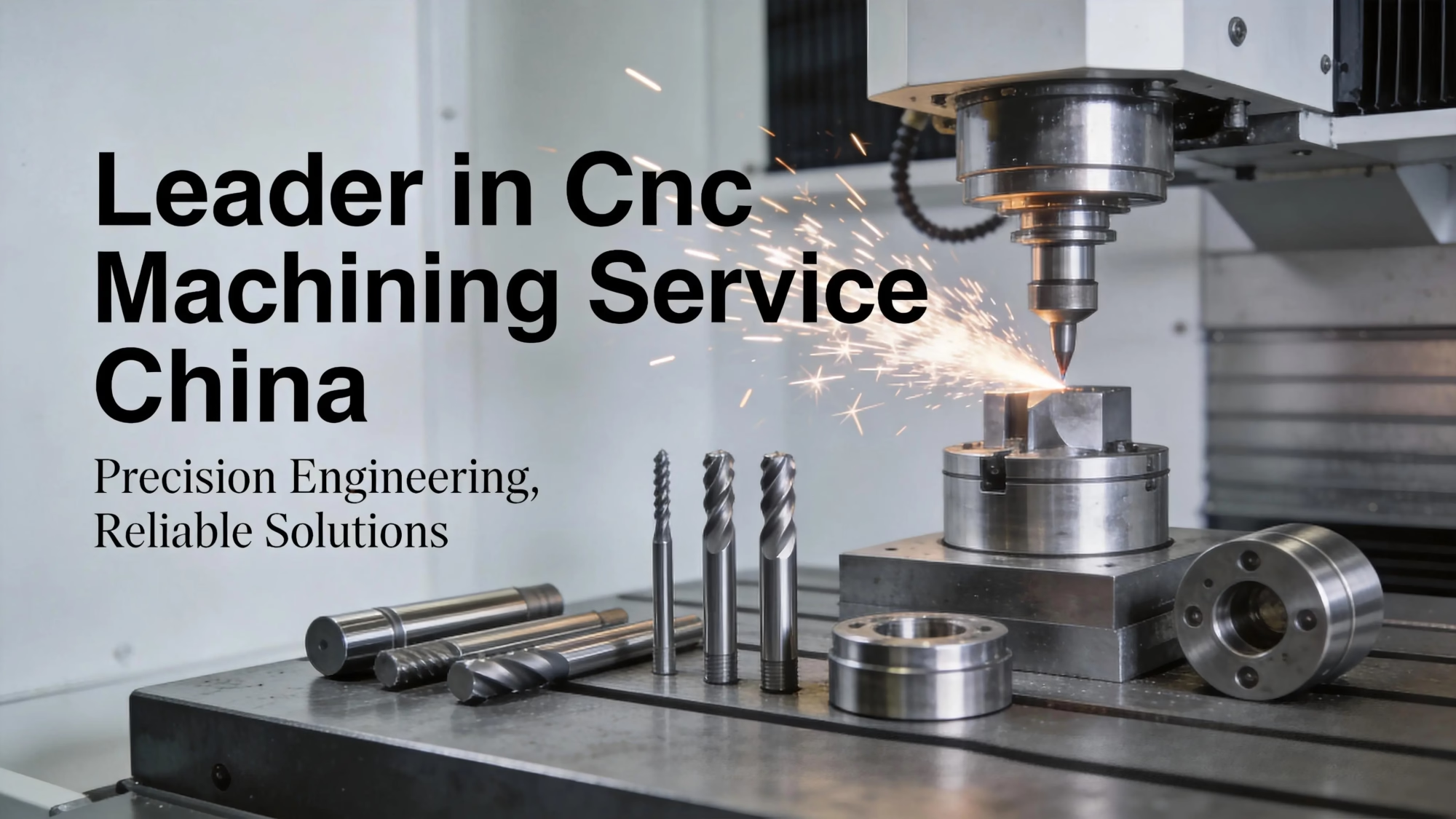
Leader in Cnc Machining Service China

Automotive and EV Drivetrains

Transmission and reducer gears where bending fatigue at the fillet sets the service interval. IATF 16949 process control from blank to final inspection.

  • Root fillet peened
  • IATF 16949
  • Ra 0.8–1.6 μm
oplus_262178

Aerospace Actuator Gears

Small, high-load gears in actuator and accessory drives. Tight fillet radii need smaller media so the shot reaches the root instead of bridging it.

  • Small fillet radius
  • Controlled intensity
  • Reported per lot
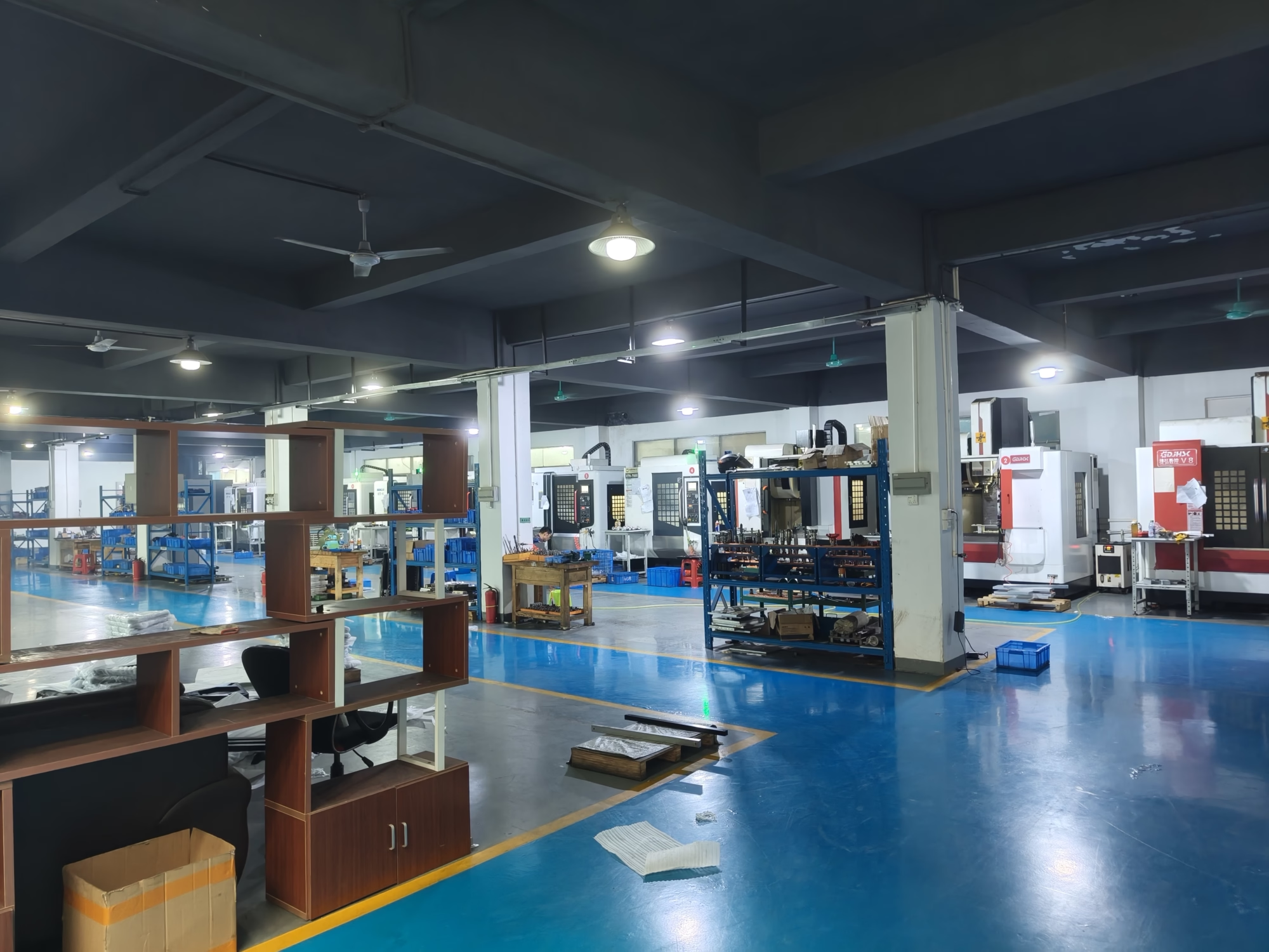
GreatLight Metal new factory building

Industrial Gearbox Components

Gears and shafts up to 4,000 mm where load capacity per tooth matters more than weight. Peening plus a corrected fillet radius raises the bending limit.

  • 4,000 mm envelope
  • High load per tooth
  • ±0.005 mm
Forge ahead with determination and create the future together.

Robotics and Automation Drives

Cycloidal and planetary stages that see millions of cycles. Coverage at the fillet and a documented Almen intensity give the fatigue model a real input.

  • High cycle count
  • Documented coverage
  • No MOQ
FAQs

Questions Engineers Ask Before Peening

Does shot peening change the gear dimensions?

It changes the surface by a very small amount, typically a few thousandths of a millimeter on the dimpled skin. That is inside our machining tolerance for most gear features.

If your drawing has a tight flank tolerance, tell us. We can leave the pre-peen dimension at the top of the band so the finished part still lands in spec.

Can I peen a gear that is already ground?

Yes, as long as the peening is the last mechanical step. Grinding after peening removes the compressive layer and leaves a fresh tensile surface at the fillet.

If a flank needs final sizing, finish the grind first, then peen. We will not grind the root fillet after peening.

Which is more important, coverage or intensity?

Both, but for different reasons. Coverage decides whether the whole stressed zone is treated. Intensity sets how deep the compression reaches.

A part with 200% coverage at low intensity has a shallow layer. A part at full intensity with 80% coverage has untreated pockets that can start cracks. We record both.

Will peening warp a thin gear or a long shaft?

It can. Peening puts one side of a thin section into compression and can bow it. Long, slender shafts are the usual risk.

We handle it with balanced peening on both sides, controlled rotation, and a straightness check after the process. For very thin webs we may recommend reducing the intensity.

Should the whole tooth face be peened or only the fillet?

The fillet is the priority because bending stress peaks there. Extending coverage across the full tooth face also helps flank pitting and oil retention.

For gears that only see bending load, fillet-only peening is a reasonable cost trade. For contact-fatigue-limited gears, cover the whole face.

How does the material grade affect the result?

Harder, higher-strength steels hold compressive stress better and hold it longer under load. 4140, 4340, and case-hardened grades respond well.

Soft, low-strength alloys and most plastics flatten the dimples without storing useful stress. We will tell you if peening is not worth the cost on your grade.

Can you peen parts you did not machine?

Yes, but we inspect first. If the fillet has a sharp grind line or the radius is under the drawing value, peening will not fix it.

In that case we quote a light machining pass to correct the fillet, then peen. That order matters more than the peening parameters themselves.

What documentation comes with a peened order?

We record media type and size, intensity, coverage, and the process sequence for each lot. Dimensional and surface reports are available on request.

Raw material check, in-process monitoring, and final inspection run on every order. 100% inspection before shipment is standard, not an add-on.

Send the Drawing, Get the Process Plan

Upload a gear drawing and we will come back with machining steps, peening parameters, and a quote within 12 hours.

12-hour quote100% inspectionNo minimum order quantityNDA on request

Trusted by engineers and manufacturers worldwide

Tesla Ford Motor Company BYD Auto Denso Magna International Boeing Airbus Medtronic KUKA FANUC