
01
Noise and vibration at operating speed
Tooth spacing error, runout on the bore, or a pitch diameter that drifts. The gearbox passes a slow bench test, then howls at 3,000 rpm. By then the housing is already machined and the fix is a new gear set.
We machine spur, helical, bevel, ring and pinion, starter ring and flywheel gears from bar stock and near-net blanks. Tight tolerances, verified geometry, no tooling charge for one-off prototypes.
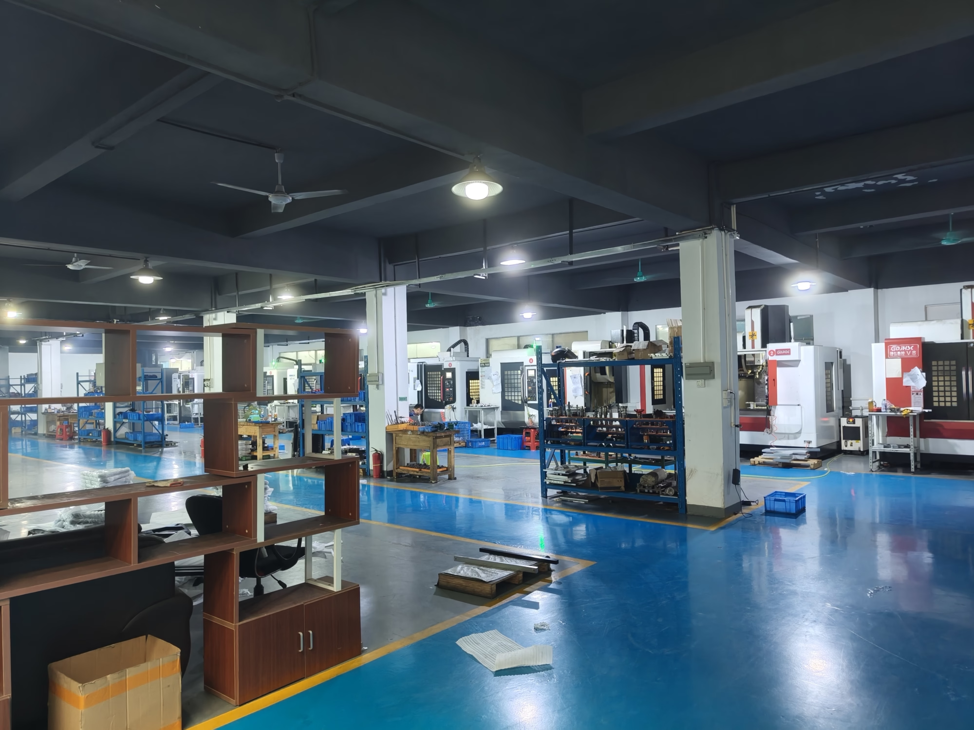
Most gear failures are decided long before the gearbox runs. These are the ones we see on incoming drawings.
Tooth spacing error, runout on the bore, or a pitch diameter that drifts. The gearbox passes a slow bench test, then howls at 3,000 rpm. By then the housing is already machined and the fix is a new gear set.
A helix angle that is slightly off, or a lead error large enough to push contact to the tooth edge. Load lands on perhaps 40% of the face width. The gear has the right hardness and still fails early.
Center distance is correct on paper, but bore-to-pitch concentricity varies from part to part. Assemblers end up sorting gears by feel instead of installing them.
A 3D model with no module, pressure angle, or profile shift defined. Two suppliers return two different quotes for two different gears. Weeks pass before anyone notices.
Turning, hobbing, milling, grinding and inspection under one roof in Dongguan.

A gear is a set of numbers before it is a part. Send a 3D model and we will ask for module or diametral pitch, pressure angle, helix angle and hand, number of teeth, profile shift, and the mating gear data. If those numbers are missing, our engineers derive them and send back a DFM note within 12 hours. You approve the data, then we cut metal.
This step catches the expensive mistakes early. A left-hand helix where a right-hand was intended, a backlash value that cannot be held at the stated center distance, a root fillet that will crack under case hardening. Fixing it in the model costs nothing. Fixing it in hardened steel costs a week.
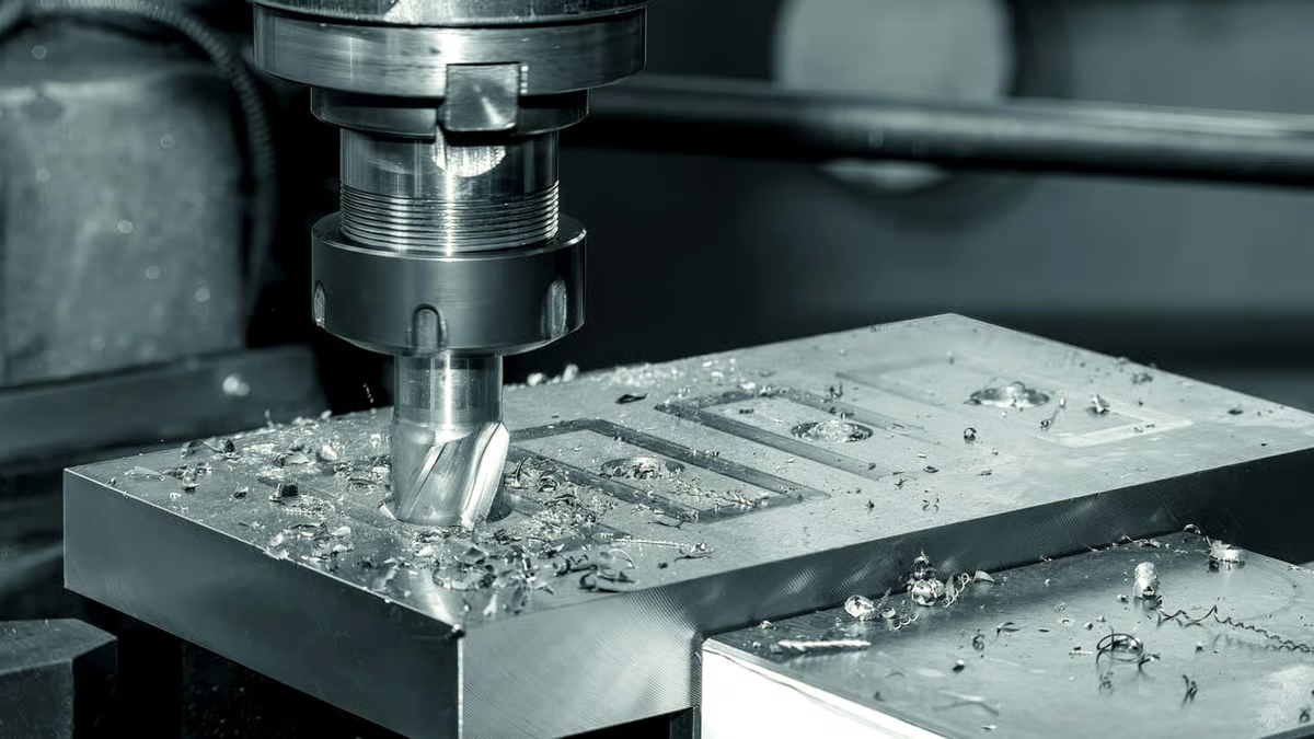
Gear blanks start on our lathes for bore, face and datum control. Teeth are cut on hobbing and milling equipment, and where the print calls for it, teeth are ground after heat treatment to bring runout and lead back into tolerance. We work in 1045, 4140, 4340, 17-4PH, 303 and 316 stainless, 6061 and 7075 aluminium, and C36000 brass.
Inspection is where a gear quote is either honest or not. We check bore diameter, face runout, pitch diameter over pins, and tooth thickness. Where a print specifies it, we check lead and profile on a gear measuring instrument. Reports go out with the parts on request. Every lot is inspected before shipment.
A short comparison for the first design conversation.
| Gear type | Best for | Watch out for |
|---|---|---|
| Spur | Parallel shafts, low speed, simple drives | Noise rises quickly above moderate speeds |
| Helical | Quiet, high load, parallel shafts | Axial thrust needs a bearing that takes it |
| Bevel | Right-angle drive, intersecting shafts | Setup sensitive, harder to correct after hardening |
| Ring and pinion | Final drive ratios in drivetrains | Lapping and contact pattern matter more than size |
| Starter ring | Engine starting, high torque pulses | Tooth chamfer and heat treat drive life |
| Flywheel gear | Energy storage and smooth power delivery | Balance and flatness tolerances are the hard part |
One card per family. If your part is not listed, send the drawing anyway.
Straight teeth for parallel shafts. Machined from bar or plate, with bore, keyway and set screw features completed in the same setup where possible. Suits low to moderate speed drives, indexing mechanisms and general machinery.
Angled teeth that spread load across more of the face and run quieter than spur. We hold helix angle and hand to print and check lead after grinding. Right-angle and parallel shaft arrangements both covered.
For right-angle power transfer between intersecting shafts. Straight and spiral configurations, cut with matched set geometry so the contact pattern lands where the design intends. High torque drives are the usual application.
Matched pairs for drivetrain ratios. We machine both members to the same gear data and keep the set together through inspection so the ratio and backlash relationship stays intact.
Ring gears for engine starting duty, where torque arrives in pulses and the teeth take repeated engagement. Chamfer, tooth form and heat treatment are specified together, not separately.
Ring gear features on flywheels and flexplate assemblies. Balance, flatness, and bolt circle position are the critical dimensions, and they are checked on the finished part, not the blank.
Values are the limits our equipment can hold, not a quote for your part.
| Item | Range | Notes |
|---|---|---|
| Maximum part size | 4,000 mm | Larger travels on selected machines |
| Rotary table | Ø400 mm | For angular features and bevel work |
| Tolerance | ±0.005 mm | Critical diameters and runout |
| Surface finish | Ra 0.2–0.8 μm | Ground tooth flanks |
| Materials | Steel, stainless, aluminium, brass, titanium | 1045, 4140, 4340, 17-4PH, 7075, C36000 and more |
| Order quantity | 1 to 10,000+ | No minimum order quantity |
| Lead time | 3–5 days | After drawing approval and material availability |
Numbers instead of adjectives.
Founded in 2011, three wholly-owned plants, 7,600 m² of manufacturing space. Gear work sits alongside the same turning and milling capability used for the rest of our parts.
Bore, pitch diameter and face runout are the features that decide whether a gear set runs quietly. Those are the ones we control to ±0.005 mm.
Angled features, bevel work and one-setup machining of complex gear bodies. 127 high-precision CNC machines in total across the plants.
Raw material check, in-process monitoring, final inspection, then 100% inspection before shipment. Reports on request.
Send a drawing and gear data. You get a price and a manufacturability note the same working day. Production can start within 24 hours after approval.
One prototype gear or a 10,000-piece run. Prototypes and production parts are machined from the same process, so the first article predicts the tenth.
Final drive and accessory gears checked to IATF 16949:2016 process discipline, with traceable inspection records per lot.

Spur and helical gears for reducers and indexing drives, where backlash consistency across a batch matters more than any single part.

Low-backlash gear pairs for joint and actuator drives, machined and inspected as matched sets so the pair behaves as designed.
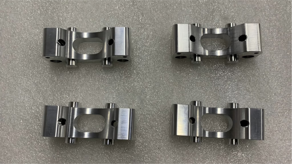
Gears and ring components where material certificates and dimensional reports travel with the parts. ISO 9001:2015 and ISO 13485:2016 systems in place.
For a gear we need module or diametral pitch, pressure angle, number of teeth, helix angle and hand, profile shift if any, and the tooth thickness or backlash target. The material, heat treatment, and the critical tolerances on bore and runout complete the picture.
If you only have a 3D model, send it. Our engineers will derive the missing values and send them back for your confirmation before quoting. That is part of the 12-hour response.
Yes. There is no minimum order quantity, so one gear and a 10,000-piece run go through the same process. For a single part we normally machine from bar stock rather than cutting a hob or a dedicated fixture.
The advantage is that the prototype uses the same machines and the same inspection method as production. If the prototype measures correctly, the production parts should too.
Teeth are cut before heat treatment, then ground afterward when the print requires it. Heat treatment moves the part, and a hardened gear that is not ground afterward will rarely hold runout or lead on its own.
If your print allows a softer material and no post-hardening grinding, we can cut to final size in one operation. That is faster and cheaper, but it limits the load the gear can carry.
Backlash comes from tooth thickness, center distance and runout together, so we check all three. Where you supply the mating gear data, we machine both members to the same gear data and keep them as a matched set.
We cannot promise a backlash value on a single gear with no mating reference. Give us the partner part or the center distance and the target becomes a real measurable number.
Common choices are 1045 and 4140 steel for general power transmission, 4340 where higher strength is needed, and 17-4PH stainless for corrosion resistance with strength. Aluminium 6061 and 7075 suit low-load or weight-sensitive gears, and C36000 brass is used for small instrument gears.
Material selection drives heat treatment, finish and cost. If you are unsure, tell us the load and the environment and we will suggest a starting point.
Every lot gets raw material verification, in-process checks, and a final inspection, then 100% inspection before shipment. Typical gear checks include bore diameter, face runout, pitch diameter over pins, and tooth thickness.
If your print calls for lead or profile measurement, we check it and can include the data in a dimensional report. Ask for the report when you place the order so it is planned into the inspection schedule.
Quotation and DFM analysis come back within 12 hours. Production can start within 24 hours after you approve the drawing and material is available. Standard parts ship in 3–5 days.
Complex geometry, heat treatment, or grinding after hardening adds time. We will tell you the added days in the quote rather than after the order.
Yes. Uploads are handled as confidential, and we can sign a non-disclosure agreement before you share gear data or drawings. There is a standard NDA available on request if your legal team prefers to start from ours.
Gear geometry is often the most sensitive part of a drivetrain design, so we treat drawings, models and gear data as customer property.
Upload your gear drawing or 3D model. We confirm the gear data, flag anything that will not machine cleanly, and price it. One prototype or ten thousand, same process.
12-hour quote100% inspectionNo minimum order quantityNDA on request
Trusted by engineers and manufacturers worldwide










Upload your 3D model or 2D drawing and get a quotation with a free DFM analysis. Maximum processing size 4,000 mm.
CNC Metals 13 grades
CNC Plastics 10 grades
Machines & processes 12 options
Surface & post-processing 10 options
Material: not selected Machine: not selected Post-process: not selected
Fill in this short form and we'll open WhatsApp with your message ready to send. We only use these details to reply to you.
Nothing is sent until you press send inside WhatsApp.