
What Do CNC Milling Machines Do?
A CNC milling machine spins a multi-edge cutter and drives it along programmed axes to remove material from a solid block. This guide explains the cutting mechanics, the axis configurations, the tolerances that hold in production, and the part shapes where milling is the wrong process. Written for design engineers and buyers who need to judge a quote, not a brochure.
In this article
- 1
- 2
- 3
- 4
- 5
- 6
- 7
Key takeaways
What do CNC milling machines do to the workpiece?
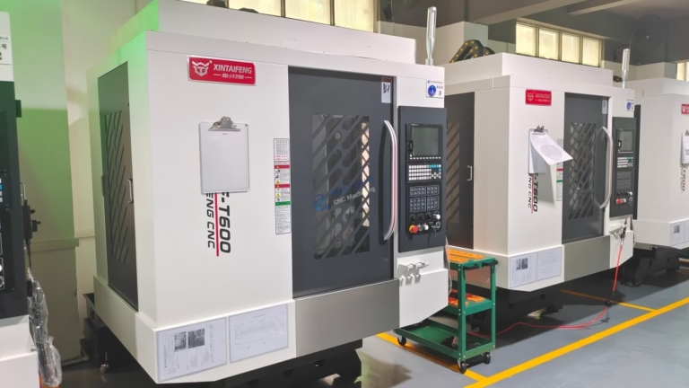
A CNC milling machine holds the workpiece still and moves a rotating cutter through it. The spindle turns the tool at a set surface speed, and the machine's axes feed the tool along a planned path. Each pass shears away a chip of metal, so the finished part is whatever remains after the cutter has walked the whole program.
The cutting edge is not a single knife. A typical end mill has two to six flutes, and each flute takes its own bite as the tool rotates. In aluminium 6061 we often run a 12 mm three-flute carbide end mill at 12,000 rpm and 3,000 mm/min feed. In 316 stainless the same tool drops to roughly 3,500 rpm and 800 mm/min, because the material work-hardens under the edge.
The machine does not know what the part should look like. A CAM programmer converts the CAD model into tool paths, sets the stock offset, and chooses the roughing and finishing strategy. The control then interpolates those paths while monitoring spindle load and axis position. Accuracy comes from that loop, plus a rigid fixture that stops the part moving.
So the short answer to what do CNC milling machines do is this: they turn a solid block into a defined shape by controlled material removal, repeating the same path on every part in the run. That repeatability is the reason the process works for one prototype and for a 10,000-part order.
- 1Roughing removes bulkLarge stepovers and high feed clear most of the stock fast.
- 2Finishing sets the surfaceSmall stepovers and a fresh tool bring Ra 0.8–1.6 μm.
- 3The fixture decides the resultA part that moves mid-cut cannot hold ±0.005 mm.
How axis count changes what the machine can cut
A 3-axis mill moves X, Y and Z only. The tool always points down, so every feature must be reachable from the top or from a re-fixtured side. That is fine for plates, brackets, pockets and housings with open faces, and it is the cheapest way to cut them.
A 4-axis machine adds a rotary table, usually Ø400 mm, that indexes or turns the part while the tool cuts. You get features on four sides without resetting the part. Long shafts, manifold blocks and parts with radial holes become one-setup jobs.
A 5-axis machine tilts the tool as well as the table. The cutter can approach a surface at an angle, which matters for undercuts, deep cavities and compound-angle faces. It also lets you keep a short, stiff tool in the cut, because the machine angles the part instead of reaching with a long tool.
The trade-off is cost and programming time. Five-axis paths take longer to verify, and the machine hour rate is higher. If a part has no undercut and no compound angle, a 3-axis setup will usually be cheaper and just as accurate.
- 13-axisPlates, pockets, open housings. Lowest cost per part.
- 24-axisShafts, radial holes, four-sided features in one setup.
- 35-axisUndercuts, deep cavities, compound angles, short stiff tools.
Which tolerances and finishes milling can actually hold
Tolerance is a system result, not a machine spec. The machine's positioning accuracy sets the floor, but the fixture, tool wear, thermal drift and material behaviour decide what you actually get. On a well-planned aluminium job we hold ±0.005 mm on critical features as a matter of routine, and ±0.0002 in for customers working in inch drawings.
Surface finish follows the same logic. A sharp tool with a light finishing pass gives Ra 0.8–1.6 μm on most metals. Push for Ra 0.2–0.8 μm and you need a dedicated finishing strategy, sometimes a smaller stepover or a separate polish step. As-machined surfaces at Ra 1.6–3.2 μm are normal for non-critical faces.
Material pushes back. 7075 aluminium and 17-4PH stainless hold tight numbers well. Thin-wall parts in magnesium AZ31B or long unsupported sections in titanium TC4 deflect under cutting force, so the tolerance has to loosen or the setup has to change. That is a process decision, not a machine limitation.
Before you call a feature impossible, ask what the tolerance is for. A non-mating face at ±0.1 mm costs far less than the same face at ±0.01 mm, and the part works just as well.
- 1Critical fits±0.005 mm / ±0.0002 in on planned features.
- 2Decorative facesRa 0.8–1.6 μm from a standard finishing pass.
- 3Non-mating surfacesRa 1.6–3.2 μm as machined is usually enough.
How different materials behave under a milling cutter
Aluminium is the easy case. Grades 6061, 6061-T6, 2024, 5052, 5083, 6063, 6082, 7075 and ADC12 all cut cleanly at high speed. They form a built-up edge if the coolant or coating is wrong, but the fix is a tool change, not a redesign.
Stainless steel is where cycle times grow. Grades 303, 304, 316, 316L, 420, 430, 431, 440C and 17-4PH (SUS630) work-harden ahead of the cutter, so the tool must stay in the cut and never rub. Feeds and speeds drop, and tool life shortens. 303 is the free-machining grade and the cheapest of the group to mill.
Steels such as 1018, 1045, 4130, 4140, 4340, A36 and tool steel behave predictably but need more spindle torque. Copper and brass grades C101, C103, C110, beryllium copper, C27400, C28000 and C36000 cut fast but are gummy, so chip evacuation matters more than speed.
Titanium TA1, TA2 and TC4 (Ti-6Al-4V), plus Inconel and magnesium AZ31B or AZ91D, sit at the difficult end. Titanium and Inconel generate heat at the cutting edge and need low surface speeds with high pressure coolant. Magnesium cuts easily but the chips are a fire risk, so the shop needs the right handling in place.
- 1Fast and stableAluminium 6061, 7075, 6082; brass C36000.
- 2Slower but reliable303, 304, 316 stainless; 4140 and 4340 steel.
- 3Needs process controlTi-6Al-4V, Inconel, magnesium alloys.
When milling is the wrong choice for a part
Milling loses to turning on round parts. If a component is mostly a body of revolution, a lathe or a mill-turn centre removes material far faster. On our 16 mill-turn centres, a shaft with cross-drilled holes comes off complete in one cycle instead of two operations.
Milling loses to casting and die casting at volume. A simple bracket at 50,000 pieces a year is cheaper as a die casting with a light finish pass. Milling wins when the geometry is complex, the volume is low, or the lead time is short. No minimum order quantity means one prototype and a 10,000-part run travel the same route.
Some shapes fight the process. Sharp internal corners need a tool radius, because the cutter is round. Deep narrow slots need long tools that deflect. Thin floors and walls vibrate. A good design change, like opening a corner radius from 0.5 mm to 2 mm, can cut cycle time and improve the result with no loss of function.
Milling also stops where the feature is smaller than the tool can reach. A 0.4 mm slot in a 50 mm deep pocket is a wire EDM or laser job, not a milling job.
- 1Mostly roundTurning or mill-turn beats milling on cycle time.
- 2Very high volumeDie casting plus a finish pass is cheaper.
- 3Sub-millimetre and deepEDM or laser, not a milling cutter.
Milling against the other processes it competes with
Use this to pick a process before you ask for a quote.
| Process | Best for | Typical tolerance | Watch out for |
|---|---|---|---|
| 3-axis milling | Plates, pockets, open housings | ±0.005 mm on planned features | Features need a second setup |
| 5-axis milling | Undercuts, compound angles | ±0.005 mm with a rigid setup | Higher machine hour rate |
| CNC turning | Shafts, bushings, round bodies | ±0.005 mm on diameters | Off-axis holes need a second op |
| Mill-turn | Round parts with cross features | ±0.005 mm in one cycle | Fewer machines available |
| Die casting | High-volume simple shapes | Finish pass sets the tolerance | Tooling cost and lead time |
| Wire EDM | Sharp corners, thin slots | ±0.005 mm and finer | Slow, and limited to through cuts |
| 3D printing | Lattice and internal channels | Looser than milling | Surface finish needs work |
Pick the process from the geometry, not the habit
If the part is prismatic with reachable faces and the volume is under a few thousand a year, mill it. If it is mostly round, turn it. If it is a simple shape at high volume, cast it. Sending a round shaft to a 3-axis mill, or a 50,000-piece bracket to a machining centre, is where money gets wasted.
Common questions
Can a CNC milling machine drill and tap as well?
Yes. Drilling, tapping, boring and reaming are standard milling operations. The spindle holds a drill or tap instead of an end mill, and the same program positions the hole.
Tapping needs the right feed and spindle synchronization. In aluminium we tap at higher speeds; in 316 stainless we slow down and use a forming tap where the thread allows it.
How small a corner radius can a milling cutter leave?
The radius equals the tool radius. A 6 mm end mill leaves a 3 mm internal corner at best.
If your drawing calls for a 0.5 mm corner, the tool would be 1 mm in diameter and too fragile for most depths. Opening the corner to 2 mm or 3 mm usually costs nothing in function and removes a real manufacturing problem.
What surface finish comes off a milling machine by default?
A standard finishing pass on aluminium or steel lands around Ra 0.8–1.6 μm.
Finer finishes at Ra 0.2–0.8 μm need a dedicated finishing strategy, sometimes a smaller stepover or a separate polish. As-machined faces at Ra 1.6–3.2 μm are normal for non-critical surfaces.
How long does a first milling run take?
We return a quotation and a free DFM analysis within 12 hours, and production can start within 24 hours of approval.
Parts ship in 3–5 days for most milling work. That figure covers programming, setup, machining and the 100% inspection before shipment.
Do you inspect every milled part before it ships?
Yes. We check incoming raw material, monitor the cut in process, and inspect the finished parts before they leave. Reports are available on request.
GreatLight holds ISO 9001:2015, IATF 16949:2016, ISO 13485:2016 and ISO 27001:2022. Uploads are confidential and an NDA is available on request.
Is there a minimum order quantity for milled parts?
No. We run from one prototype to 10,000+ part runs on the same machines and the same process.
For a single part, the setup is the main cost. For a 10,000-part run, cycle time and tool life dominate. Both cases go through the same 127-machine shop.
Send a drawing and get a real process answer
We will tell you which axis configuration and which process fit the part, and flag any feature that will cost more than it needs to.
12-hour quoteFree DFM analysis100% inspectionNo MOQ
More from the shop floor
We publish setup notes, tooling trials and inspection data from the factory floor.











