
What Is CNC Milling: How a Rotating Cutter Shapes Metal
CNC milling is a subtractive process: a multi-tooth cutter spins while the machine drives it along programmed paths, peeling metal off a solid block. This page covers the mechanics, the axis configurations, the practical tolerance limits, and the part shapes that suit milling. It is written for design and process engineers deciding whether milling is the right call.
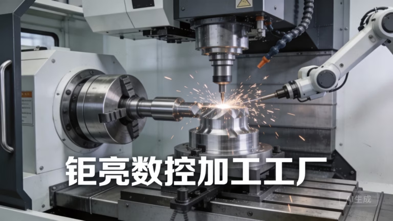
What is CNC milling doing to a block of metal?
Milling is subtractive. You start with bar, plate, or a cast block, and a rotating cutter removes material until the geometry matches the drawing. The cutter carries several teeth, so each revolution takes many small chips. Feed per tooth, spindle speed, and radial depth of cut together set the chip load. Chip load is what decides whether the tool shears metal cleanly or rubs, heats up, and work-hardens the surface.
The CNC part is the control loop. G-code carries coordinates, feed rates, and spindle commands. The controller turns that into motion through servomotors, and glass scales or encoders close the position loop thousands of times per second. A hand mill depends on an operator reading a dial and feeling the cut. Nothing about that is repeatable across a 500-part run.
That repeatability is why what is CNC milling sits closer to a manufacturing system than to a single machine. The same program, run on the same machine, produces the same tool path on part one and part five hundred. Change the program and you change the part, not the setup skill level.
One boundary worth stating early: milling removes material, so it cannot produce internal cavities that a tool cannot reach. Deep pockets with a small corner radius, long bores, and internal threads all run into tool reach before they run into machine accuracy.
The parts that decide accuracy
The spindle holds the tool and turns it. On a production machine it runs on ceramic or steel bearings with preload, and its runout sets the floor on wall thickness variation. A spindle with 5 μm of runout cannot hold a ±0.005 mm bore no matter what the controller claims.
The linear axes move the table or the column. Box ways carry heavy cuts and damp vibration; linear guides run faster with less stick-slip. Both work, and the choice usually follows the part mix rather than the spec sheet.
The ballscrew turns motor rotation into linear motion. Its lead error and thermal growth show up directly in part length, which is why shops that hold tight tolerances run warm-up cycles before the first cut and keep the shop temperature steady.
The tool changer and the workholding are quieter contributors. A pull-stud that seats badly adds runout. A vise that lifts the part on the last pass moves the finished face. We check both before blaming the program.
Where what is CNC milling stops being the right answer
Tolerance is the first limit. On a rigid 5-axis center we hold ±0.005 mm (±0.0002 in) on features the tool can reach with short, stiff tooling. Stretch that tool out to a 6:1 length-to-diameter ratio and the same machine drifts. The tolerance is a property of the whole setup, not of the model number.
Surface finish follows the same logic. Ra 0.8–1.6 μm is a normal milled finish. Ra 0.2–0.8 μm is reachable with fine stepover and a sharp cutter, but it costs time. If the drawing calls for a mirror finish on a large face, grinding or polishing usually beats milling it.
Geometry sets the other boundary. Sharp internal corners cannot be milled. The cutter has a diameter, so every inside corner carries that radius. A 6 mm cutter leaves a 3 mm corner radius. Designers who mark a sharp internal corner force the shop to either use a tiny cutter, which is slow and fragile, or add EDM, which adds cost and lead time.
Quantity matters too. For one prototype, milling is often the fastest route from a model to a metal part. At 100,000 units, die casting or forging plus a finishing cut usually wins on cost.
How material choice changes the cut
Aluminum is the easy case. Grades like 6061-T6, 7075, and 6082 cut fast with high rake tooling and generous feed. They also move with heat, so thin walls can spring back after the vise releases. Rough, stress-relieve if the part is thin, then finish.
Stainless is where shops earn their money. Grades 303 and 304 work-harden if the tool rubs instead of cuts. Feed per tooth has to stay above the rubbing range, and coolant has to reach the edge. 17-4PH in the H900 condition is harder again and calls for reduced stepover.
Titanium TC4 (Ti-6Al-4V) conducts heat poorly, so the heat stays in the cutter. Cutting speeds drop, coolant volume rises, and tool life is measured in minutes on roughing. The payoff is strength-to-weight that aluminum cannot match.
Plastics are not a soft option. POM and PEEK machine cleanly with sharp, polished flutes and high spindle speed. ABS and PC melt and smear if the chipload is too low. On carbon fiber, edge quality depends on the fiber direction, and tool wear is abrasive.
Parts that suit what is CNC milling
Prismatic parts with pockets, slots, and bolt patterns are the natural fit. Housings, brackets, manifolds, and fixture plates all fall into this group. The tool approaches from a small number of directions, so setups stay simple and inspection is straightforward.
Sculpted surfaces need simultaneous 5-axis. Impellers, turbine blades, and organic housings cannot be reached with a 3-axis setup because the tool would collide with the part long before it reached the surface. Five-axis keeps the cutter normal to the surface, which also improves finish.
Prototypes and low-volume runs are the other strong case. With no minimum order quantity, a single part can be machined from the final material, not a stand-in. That means the prototype behaves like the production part on the test bench.
What milling is poor at: thin walls below roughly 0.5 mm in aluminum, deep narrow slots, sharp internal corners, and very high volumes of a simple shape. In those cases, sheet metal, EDM, or casting usually fits better.
Choosing an axis configuration
More axes add reach and setup reduction, not automatic accuracy.
| Configuration | Typical travel | Best fit | Watch out for |
|---|---|---|---|
| 3-axis | 500 × 500 × 450 mm | Prismatic parts, open faces, plate work | Undercuts need a second setup |
| 3-axis | 750 × 1,150 × 550 mm | Large plates, fixtures, housings | Long tools deflect in deep pockets |
| 4-axis | Ø400 mm rotary table | Shafts, flats around a bore, tube features | Indexing only unless the control interpolates |
| 5-axis simultaneous | Up to 4,000 × 400 × 150 mm | Impellers, blades, sculpted surfaces | Cost per hour is higher; use it when needed |
| Mill-turn | Up to 4,000 mm length | Round parts with milled flats and holes | Not for large box shapes |
| Benchtop / 3-axis small | 500 × 310 × 200 mm | Prototypes, small brackets, jigs | Limited rigidity on hard steels |
The short version
If the part is prismatic, needs tight tolerances, and the volume is under a few thousand units, milling is the direct route. If the shape is a thin shell or a high-volume simple form, pick another process before you optimize the tool path.
Common questions
What is the difference between CNC milling and CNC turning?
Milling spins the tool and holds the workpiece still. Turning spins the workpiece and holds the tool still.
That difference decides the part shape. Round parts with axial symmetry belong on a lathe. Parts with pockets, flats, and holes on several faces belong on a mill. A mill-turn center does both in one setup.
How tight a tolerance can milling hold?
On features the cutter can reach with a short, rigid tool, ±0.005 mm is achievable on a well-maintained 5-axis center.
That number degrades with tool length. Past a 6:1 length-to-diameter ratio, deflection takes over and the practical limit loosens considerably.
What surface finish does milling leave?
As-machined milling sits around Ra 1.6–3.2 μm. A controlled finish pass with fine stepover reaches Ra 0.8–1.6 μm.
Below Ra 0.2 μm usually means a secondary operation such as polishing, lapping, or grinding rather than a different tool path.
Can milling make a part with a sharp internal corner?
No. The cutter has a diameter, so every internal corner carries a radius equal to half that diameter.
If the drawing truly requires a sharp corner, expect a small cutter with slow feed or an EDM operation added to the route.
Is milling cheaper than 3D printing for prototypes?
It depends on geometry and material, not on the process name. A simple bracket in aluminum is often cheaper milled because the material is cheap and the setup is short.
A hollow lattice with internal channels is cheaper printed because milling cannot reach the internal geometry at all.
How many parts can be milled economically?
From a single prototype up to a few thousand units, milling usually stays competitive because setup is short and no tooling is needed.
Above that, casting, forging, or stamping usually wins once the tooling cost is amortized over the run.
Send a drawing, get a real answer
We review the geometry, suggest the axis configuration, and quote with a DFM note on what is CNC milling doing for your part and what it cannot do.
12-hour quote100% inspectionNo minimum order quantity
More from the shop floor
We publish setup notes, tooling trials and inspection data from the factory floor.











