
What Does a CNC Machine Look Like?
Most people picture a grey box with a door. That picture is right, and it hides everything that matters. This page shows what a CNC machine look like outside and inside, what the main parts do, and which visual details tell you what a shop can actually hold tolerance on.
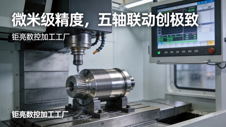
What a CNC Machine Look Like From the Aisle
Walk down the aisle of a modern shop and you cannot see the cutting. You see a cabinet. A machining center is a fully enclosed steel box with a sliding door, a control pendant on a swivel arm, and a chip conveyor sticking out one side. The door is not decoration. It keeps chips and coolant inside, and it keeps hands out of a spindle turning at 12,000 rpm.
Size is the fastest clue to capability. A compact 3-axis vertical mill sits in a footprint near 2 m × 2 m and cuts a 500 × 500 × 450 mm envelope. A gantry-style machine with a 4,000 × 400 × 150 mm travel takes up most of a bay and needs a foundation. If a supplier lists a 4,000 mm maximum processing size, they are talking about long parts such as extruded frames, not about a small bracket.
Look at the floor. Big machines sit on isolated pads, sometimes with leveling wedges you can see under the base. Thermal growth moves a casting by tens of microns over a shift, so shops that chase ±0.005 mm keep the machine in a temperature-controlled room. A machine parked next to an open loading dock will cut a different part in the afternoon than it did at 6 a.m.
- 1EnclosureFull sheet-metal cabinet; the door interlock stops the spindle when opened.
- 2Control pendantSwivel arm with screen and MPG handwheel for setup.
- 3Chip conveyorAuger or hinge-belt on the side; a clear sign of production use.
- 4Leveling padsVisible under the base; large machines sit on isolated concrete.
Open the Door: What Sits Inside the Enclosure
With the machine stopped and the door open, the work zone is a compact stage. The spindle nose points down at the table, and the table carries a vise, a 3-jaw chuck, or a fixture plate. Way covers, usually steel or folded bellows, shield the linear guides from chips. Coolant nozzles ring the cut and flood the zone with an oil-water emulsion, both to lubricate and to carry heat away.
Heat is the quiet enemy. A 10 mm carbide end mill running at 8,000 rpm puts real thermal load into the tool and the part. If coolant flow drops, the tool grows, the part grows, and the last hole in a 40-hole pattern no longer matches the first. That is why coolant-through-spindle is common on production machines and why nozzle position matters more than most operators admit.
Look for the tool magazine. On a vertical mill it is often a carousel on the side of the column, holding 20 to 40 tools. On a horizontal or mill-turn machine it can be a chain magazine holding 60 or more. Automatic tool change is what lets a part go from drill to end mill to tap without an operator touching the machine between operations.
- 1SpindleTaper interface (BT30, BT40, HSK) drives the toolholder; speed sets the surface finish.
- 2Table and fixtureT-slots or a zero-point plate locate the workpiece.
- 3Way coversProtect guides and ballscrews from abrasive chips.
- 4Coolant ringMultiple nozzles aimed at the cut, not at the door glass.
Axes, Spindles and What the Motion Hardware Tells You
A 3-axis machine moves the table in X and Y and the spindle in Z. Add a rotary table and you get 4-axis work, where the part rotates between cuts. A true 5-axis machine moves the tool around the part on five simultaneous axes, which lets a single setup cut undercuts, angled ports, and blended surfaces that would otherwise need three separate fixtures.
Simultaneous 5-axis is not the same as 3+2. In 3+2 the table indexes to an angle and locks, then the cut runs in three axes. That is fine for a part with flat faces at fixed angles. Simultaneous motion is what you need for an impeller, a turbine blade, or a medical implant with a continuous freeform surface. Ask which one a shop has before you send a curved part.
The rotary table size sets a hard limit. A Ø400 mm table with a typical chuck can hold a part roughly 300 mm across before the corners swing past the travel limits. Larger parts need a bigger table or a different machine. This is why a shop will sometimes tell you a part fits the envelope but still cannot be cut in one setup.
- 13-axisPrismatic parts, plates, housings; simplest and cheapest to program.
- 24-axisShafts, cylinders, parts with features on four sides.
- 33+2Indexed angles; good for flat faces, no blended curves.
- 4Simultaneous 5-axisFreeform surfaces, undercuts, single-setup complex parts.
Turning Centers and Swiss-Type Machines Look Different
A CNC lathe does not look like a mill. The work rotates and the tool stays still. You see a chuck or a collet at the left of the work zone, a turret of tools on a slide, and a tailstock on the right for long shafts. Enclosed lathes often have a bar feeder bolted to the back, a long tube that pushes 3 m bar stock into the spindle without stopping the cycle.
A Swiss-type machine is narrower and longer. Bar stock feeds through a guide bushing right at the cutting zone, so the tool always cuts within a few millimeters of the support point. That is how shops hold ±0.005 mm on a 6 mm diameter medical pin that would deflect on a conventional lathe. The trade-off is bar diameter: most Swiss machines top out well under 32 mm.
Mill-turn centers combine both. A turret with live tooling and a B-axis head can mill a flat, drill an off-axis hole, and turn the outside diameter in one cycle. For a part like a hydraulic manifold with cross-drilled ports, this removes a second op and a second fixture, which usually removes a stack of tolerance error too.
- 1CNC latheChuck or collet, turret, tailstock; round parts up to large diameters.
- 2Swiss-typeGuide bushing, long slender parts, small diameters, tight tolerance.
- 3Mill-turnTurning plus live tooling; fewer setups, less accumulated error.
- 4Bar feederLong tube at the rear; runs unattended for hours.
What Each Visible Feature Tells You
Use this when you walk a shop floor or review machine photos from a supplier.
| What you see | What it usually means | When it is the wrong choice |
|---|---|---|
| Compact 3-axis mill | Plates, brackets, simple housings | Freeform surfaces needing 5 axes |
| Carousel ATC, 20-40 tools | Multi-tool jobs in one setup | Very long cycle with 80+ tools |
| Chain magazine, 60+ tools | Lights-out production runs | One-off prototypes, tooling cost not repaid |
| Ø400 mm rotary table | Parts up to roughly 300 mm across | Large housings that swing past travel |
| Bar feeder at the rear | High-volume small turned parts | One-off shafts cut from plate |
| Guide bushing (Swiss) | Long slender parts, tight tolerance | Bar over 32 mm diameter |
| Temperature-controlled room | Tolerance work near ±0.005 mm | Roughing or non-critical brackets |
| Open machine, no enclosure | Legacy or manual-assisted work | Any job needing coolant or chip control |
Which Machine Shape Fits Your Part
If your part is prismatic with flat faces and holes, a 3-axis or 3+2 mill is the right and cheaper answer. If it has a continuous curved surface or an undercut you cannot reach from one direction, you need simultaneous 5-axis, and a shop without it will either refuse the job or split it across three fixtures with worse tolerance. If it is round and slender, go to a Swiss-type, not a mill.
Questions Engineers Ask After the Tour
Can I tell a machine's accuracy just by looking at it?
No. Enclosure size, spindle taper and the number of axes tell you what geometry the machine can reach, not how well it holds it. Accuracy comes from the casting, the ballscrew class, the feedback system, and the room temperature.
A better signal is the shop's inspection routine. A supplier that checks raw material, monitors in-process and inspects 100% before shipment is telling you more than a photo of a large machine.
Is a bigger machine always more capable?
Not for small parts. A large machine has more thermal mass and a longer axis travel, so it moves further to reach a small feature. For a 20 mm medical component, a compact machine in a controlled room usually wins.
Match the envelope to the part. A 4,000 mm gantry is the right tool for an extruded frame and the wrong one for a valve body.
What does a 5-axis machine look like compared with 3+2?
Both may look identical from the aisle. The difference is in the control and the rotary axes. On a 3+2 machine the trunnion or table indexes to an angle and locks before the cut. On a simultaneous machine all five axes move together through the whole toolpath.
Ask the supplier to describe the last curved part they cut. If the answer involves indexing to three positions, it was 3+2.
Why do some machines have a long tube at the back?
That is a bar feeder. It pushes bar stock into the spindle so the machine can run part after part without an operator loading each blank. On a Swiss-type it also feeds through the guide bushing.
Bar feeders suit high-volume turned parts. For a one-off shaft cut from plate, the tube is just unused hardware.
What surface finish can I expect from a standard machine?
As-machined surfaces typically land around Ra 1.6–3.2 μm. A controlled finishing pass with the right tool and coolant reaches Ra 0.8–1.6 μm. Fine finishing down to Ra 0.2–0.8 μm needs a dedicated pass, sharp tooling and a stable setup.
Finish is a process choice, not a property of the cabinet you see from the aisle.
How many axes do I actually need for my part?
Count the directions you must reach from. Holes and flats on top and sides: 3-axis with two setups, or 3+2 in one. Ports at compound angles or a blended curve: simultaneous 5-axis.
Every added axis removes a setup and its tolerance stack, but it also raises programming and machine-hour cost. Choose the smallest axis count that reaches every feature cleanly.
Send Us the Part and We Will Match the Machine
Upload a STEP file and we will review the geometry, tell you which machine class fits, and quote within 12 hours with a free DFM note on features that will not cut cleanly.
12-hour quote100% inspectionNo minimum orderNDA on request
More from the shop floor
We publish setup notes, tooling trials and inspection data from the factory floor.











