
What Does Home Position Mean for a CNC Machine?
Home position is the reference the control trusts before any tool moves. This page explains how a machine finds it, what breaks it, and which parts actually depend on it. Written for engineers and buyers who need to judge a shop's setup discipline, not just its spindle count.
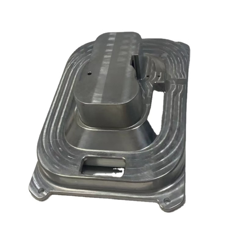
What home position for a CNC machine actually is
Home position for a CNC machine is the fixed point the control uses as its own origin. Every coordinate in the program is measured from there. It is not the corner of your blank, and it is not the datum your drawing calls out. It is where the machine believes it is standing.
When you power up, the control has no idea where the axes are. Encoders on most machines are incremental, so they count movement, not absolute place. Homing is the sequence that drives each axis against a hard stop or a reference switch, then loads a stored number into the control. From that moment the machine knows its own geometry.
This is why the first move after power-up is often a slow crawl instead of a rapid. The control is looking for the switch, not cutting metal. Push it too fast and the axis can overshoot the trip point, which repeats as a small offset on every part in that run.
Some mills keep absolute encoders and a battery-backed position. They can skip the crawl and resume straight from the last shutdown. The trade is that the stored offset has to be right. A battery failure or a contaminated scale turns that convenience into a silent shift nobody notices until the first article is scrapped.
- 1Machine zeroThe control's own origin, set by homing. Not the part datum.
- 2Work offsetG54 to G59, where the operator tells the control the blank sits.
- 3Reference switchThe physical trip point the axis hunts during homing.
How homing runs on a 3-axis mill
A typical homing cycle starts on Z. The spindle climbs until it clears the tallest fixture in the envelope, then the switch trips and the control backs off a set distance. Only after Z is safe do X and Y move. That order exists to keep a tool from dragging across a vise jaw on the way home.
Once the switches are found, the control applies a grid shift. Every switch has a repeatability of its own, usually a few microns, so the builder stores a correction that pins the mechanical trip to a nominal position. This is why the number in the control rarely matches the physical switch location.
The cycle ends with the axes parked at a safe point, often the machine's own far corner. From there the operator loads a work offset, touches off the blank, and the program runs in part coordinates. Home never changes during that run. It only changes if the machine is re-homed.
On a 5-axis machine the same idea applies to A and B. The rotary axes have their own reference, and they must be found before any simultaneous move. If the tilt axis homes to the wrong side of zero, the tool vector in the CAM file points somewhere the machine cannot reach. We see that most often after a crash, not after a normal shutdown.
- 1Z firstClear the fixture before X and Y travel.
- 2Grid shiftStored correction that maps switch trip to nominal.
- 3Park positionSafe point, not a cutting position.
Where home error shows up in the part
A homing offset moves the whole coordinate system. It does not change the shape of the part. If the machine is 0.03 mm off, every feature on every part is 0.03 mm off in the same direction. That is the signature you look for: a consistent shift across a batch, not random scatter.
Random scatter points somewhere else. Tool wear, thermal growth, and fixture clamp-up move features around without a common direction. A uniform offset across a run, especially after a power event or a maintenance visit, is the pattern that says the reference moved.
This matters most on parts with two setups. If Op 1 and Op 2 are homed on the same machine, a shift cancels out. If Op 2 runs on a second machine, a 0.02 mm difference between the two references lands directly on the feature that ties the two sides together.
For parts held at ±0.005 mm, that is the whole budget. A bore pattern, a dowel pin location, a mating face: anything that has to line up with a feature cut in another setup inherits the error in full. Features cut in one setup from one reference do not.
- 1Uniform shiftPoints to the reference, not the cutter.
- 2Random scatterPoints to tool wear, heat, or clamping.
- 3Multi-setup partsInherit the difference between two references.
When home position does not matter much
Single-setup parts are forgiving. If a bracket is cut entirely in one orientation with no re-fixturing, the reference only has to be repeatable within the run. A small absolute offset changes nothing, because the operator touches off the blank and the part comes out the same size.
Parts with generous tolerances are the same story. A mounting plate at ±0.1 mm does not care about a 0.02 mm reference shift. Chasing homing accuracy on that part wastes setup time. The effort belongs on the features that actually have a tight callout.
What does matter is repeatability, even on loose parts. If the reference drifts between the first article and the last, the operator re-touches the offset mid-run and burns cycle time. A machine that homes the same way every morning is worth more than one with a tighter spec sheet and a wandering switch.
The hard stop is the machine envelope. A 4,000 mm bed with a 4,000 × 400 × 150 mm travel has a real end to X. Homing near that end, then running a long part, can leave no room for the tool to clear. Setup planning has to account for where home sits, not just where the part sits.
- 1One setupAbsolute offset rarely shows on the part.
- 2Loose tolerance±0.1 mm work ignores small shifts.
- 3RepeatabilityStill matters for cycle time and first article.
Reading a position problem from the evidence
Match the symptom to the likely source before touching the control.
| Symptom | Likely source | Check first |
|---|---|---|
| Every feature shifted one way | Homing offset or grid shift | Re-home and compare to last known number |
| Features scattered both ways | Tool wear, heat, clamping | Tool offset log and spindle warm-up |
| Op 1 and Op 2 do not line up | Two machines, two references | Dowel or bore measured on both setups |
| Shift after a power cut | Battery-backed encoder lost offset | Encoder battery and scale condition |
| Shift after a crash | Reference switch or coupling moved | Switch trip point and axis backlash |
| Shift after maintenance | Service moved a hard stop | Re-home and re-touch all work offsets |
The call we make on the floor
If the part runs in one setup at ±0.01 mm or looser, home accuracy is housekeeping. If it spans two setups or holds ±0.005 mm, the reference is part of the tolerance stack and needs a documented re-home after any power event, crash, or service visit.
Common questions
Is home position the same as the work offset?
No. Home is the machine's own origin, set by the homing cycle and stored in the control. The work offset is where the operator tells the control the blank sits, usually in G54 through G59.
Home can move only if the machine is re-homed. The work offset changes on every new setup, sometimes several times a day.
How often should a machine be re-homed?
At every power-up on a machine with incremental encoders. That is the normal cycle, not a repair.
On a machine with absolute encoders and a healthy battery, the control can keep its position across shutdowns. We still re-home after any crash, service visit, or unexplained dimension shift, because those are the events that move a switch or a coupling.
Can a homing error be corrected in the program?
You can shift the work offset to compensate, and that is what most operators do to finish a run. It is a patch, not a fix.
The stored grid shift in the control will still be wrong, so the next setup inherits the same error. Correct the reference first, then re-touch the offsets.
Does a warm machine hold home better?
Thermal growth moves the structure, not the reference switch. The switch trip point is mechanical, so it stays put while the column and bed grow a few microns.
That growth shows as a slow drift over the first hours of a run, which is why we let a machine warm up before cutting tight features. It is a separate effect from homing, and it is handled with warm-up cycles, not with re-homing.
What changes on a 5-axis machine?
The rotary axes need their own reference before any simultaneous move. If A or B homes to the wrong side of zero, the tool vector no longer matches the CAM file.
That failure is easy to spot: the tool approaches from an unexpected direction or the control throws a soft limit alarm before the cut starts. Re-home the rotary axes and re-post the program.
Does home position affect surface finish?
Not directly. Finish comes from tool geometry, feed per tooth, spindle speed, and rigidity. A reference offset moves the part in space, it does not change Ra.
Indirectly it can matter. If an operator compensates a shift by pushing a tool deeper, the changed radial engagement can show in the finish on a thin wall.
Send us the drawing and we will check the setup plan
Quotation and free DFM analysis within 12 hours. Uploads are secure and confidential, and an NDA is available on request.
12-hour quote±0.005 mm tolerance100% inspection
More from the shop floor
We publish setup notes, tooling trials and inspection data from the factory floor.











