
3 Axis CNC Machine File Format: What to Send
The best 3 axis cnc machine file format is the one that carries your design intent without translation loss. STEP is the default for solid parts, DXF for 2D profiles, STL only for rough checks. This page explains how each format survives the trip from CAD to G-code on a 3-axis mill.
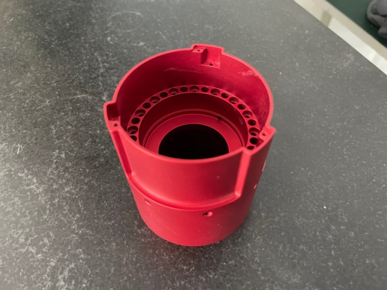
How a File Becomes G-code on a 3-Axis Mill
A 3-axis machine moves the tool in X, Y and Z. The table holds the part, the spindle comes down from one direction. That single setup direction is why the 3 axis cnc machine file format matters so much. Any surface the tool cannot reach from the top or the side needs a second setup, or it does not get machined at all.
Your file is not what the machine reads. CAM software reads the file, rebuilds the geometry, then writes toolpaths and G-code. If the rebuild is wrong, the toolpath is wrong. A hole that arrives as two half-cylinders, or a face that arrives as a mesh of triangles, gives the programmer nothing exact to work from.
So the question is not which format is modern. It is which format keeps edges, faces, cylinders and tolerances intact when it leaves your CAD seat and lands in our CAM seat. That is a narrower question, and it has a clear answer most of the time.
One more constraint sits on top. A 3-axis tool reaches straight down. Undercuts, deep side pockets and features on the back face are invisible to a single setup. No file format fixes that. The geometry itself has to suit the process.
- 1Surfaces over trianglesExact faces drive exact toolpaths; meshes only approximate them.
- 2Units declaredMillimeters or inches, stated in the file header, not assumed.
- 3One solid, one coordinate systemWCS at a real datum saves a setup decision later.
What Each 3 Axis CNC Machine File Format Actually Carries
STEP (AP203, AP214, AP242) is a boundary-representation solid. It stores analytic surfaces, so a Ø8 mm hole stays a true cylinder with a real axis. It moves cleanly between SolidWorks, NX, Creo, Fusion 360 and Inventor. For milled brackets, housings, plates and manifolds, this is the format we ask for first.
IGES is the older exchange standard. It also stores surfaces, but it can split a single face into trimmed patches and sometimes leaves small gaps at the seams. Those gaps matter when you need ±0.005 mm. IGES still has a place for legacy parts and for free-form surfaces, but for new work STEP is the safer container.
STL is a mesh. It has no units, no feature names, no tolerance data, and no way to say where a hole axis sits. A coarse STL of a curved surface shows visible facets. Sending only STL means the programmer rebuilds your part by hand, and any dimension they guess is a risk you carry.
DXF and DWG are 2D. They are perfect for flat profiles, plate outlines, bend lines and waterjet or laser blanks. For a 3-axis milled 2.5D part, a clean DXF of the profile plus a STEP of the solid covers almost every question.
Parasolid (X_T) and native files such as SLDPRT, PRT and IPT are exact too. We can read them, but each brings a version dependency. A native file from a CAD release we cannot open is a delay. STEP removes that variable.
3MF and OBJ are mesh families, same limitations as STL. PDF drawings are not geometry at all, but they are still valuable as a tolerance and finish reference. Send the model and the drawing together.
Which Geometry Survives 3-Axis Machining
Three-axis work favors prismatic parts: flat top faces, through holes, counterbores, tapped holes, straight pockets and stepped profiles. If you can describe the part as a series of cuts from above, the file translation is usually clean and the toolpath is short.
Trouble starts with curvature that wraps around the part axis. A radial slot, a side undercut or a spherical boss on a vertical wall cannot be reached with the tool pointing down. You either rotate the part into a new setup or move the job to a 4-axis or 5-axis machine.
Wall height drives tool choice. A deep pocket with a 3:1 depth-to-diameter ratio needs a long, thin end mill that deflects under load. Expect a looser tolerance on that wall than on a shallow one, no matter how clean the STEP file is.
Thin floors and tall ribs move during cutting. A 0.8 mm floor on a 6061 plate will spring back after the last pass. Adding a finishing pass with light radial engagement helps, and a stress-relieved blank helps more.
Sharp internal corners are physically impossible. Every end mill has a corner radius. If your STEP model shows a true 90° internal corner, the machined part will show the cutter radius instead. Design the radius you can live with, usually 0.5 mm to 3 mm.
Threads should be modeled or called out. A modeled thread in STEP is fine, but a callout on the drawing is what the programmer actually uses. State the standard, the class and the depth.
File Checks Before You Upload
Run a quick self-check first. It takes five minutes and prevents most of the back-and-forth. Open the exported file in a viewer, not in your CAD. If it opens wrong in a neutral viewer, it will open wrong in CAM.
Confirm units. A part exported in inches and read as millimeters comes out 25.4 times too large. This is the single most common export error we see.
Look at the model as a machinist would. Rotate it so the spindle points down. Can every feature be reached? Mark the ones that cannot, and tell us which face they sit on.
Send the drawing with the model. The model gives geometry, the drawing gives intent: datums, tolerances, surface finish, thread class and material. When the two disagree, the drawing wins unless you say otherwise.
Note the critical dimensions. If two holes must sit within ±0.005 mm of each other, say so. Everything else can sit at a wider, cheaper tolerance, and the quote reflects that.
Keep the upload channel secure. Contract parts often carry IP. Send through our upload form or request an NDA before you share the STEP file.
- 1One part per fileAssemblies slow the CAM rebuild and hide the part you want quoted.
- 2Datum at a real facePut the origin on a surface the machine can touch.
- 3Name the revisionREV-A, REV-B in the filename stops wrong-version cutting.
What Happens to Your File in Our Shop
A STEP file lands in CAM, gets checked against the drawing, and becomes a setup plan. We pick the blank size, the workholding and the order of operations. For a 3-axis job, that usually means a vise or a fixture plate, top face first, then flip for the back.
During the DFM review we flag anything that will cost you money: a corner radius too small for the feature depth, a tolerance tighter than the process holds, a wall too thin to clamp. We send that analysis back with the quote, usually within 12 hours.
Our three-axis capacity covers 27 machines, with travels up to 4,000 × 400 × 150 mm and compact cells at 500 × 500 × 450 mm. Parts hold ±0.005 mm and finishes from Ra 0.2–0.8 μm to Ra 1.6–3.2 μm as machined.
Materials run from 6061-T6 and 7075 aluminium to 17-4PH stainless, 4140 steel, C36000 brass, Ti-6Al-4V and PEEK. Each behaves differently at the cutter, which is why the DFM note sometimes suggests a different alloy rather than a different file.
3 Axis CNC Machine File Format Comparison
Exact geometry beats meshes for anything dimensioned.
| Format | Type | Best for | Main risk |
|---|---|---|---|
| STEP | Exact solid | Milled 3D parts, most jobs | Version mismatch on old readers |
| IGES | Exact surfaces | Legacy parts, free-form surfaces | Trimmed faces and seam gaps |
| Parasolid X_T | Exact solid | Shops running Siemens NX | Reader version dependency |
| STL | Triangle mesh | Visual check, 3D printing | No units, no features, faceted curves |
| DXF / DWG | 2D wireframe | Plate profiles, bend lines | No Z depth or 3D features |
| 3MF / OBJ | Mesh | Slicing and colour models | Same limits as STL |
| Native CAD | Exact solid | Fast handoff inside one CAD | Cannot open the wrong release |
Which Format to Send
For a milled 3D part, send STEP plus a PDF drawing. For a flat 2.5D profile, send DXF plus a STEP solid. Use STL only as a visual reference, never as the only file. If your CAD cannot export STEP, send Parasolid and tell us the release.
File Format Questions
Is STEP always better than IGES?
For solid parts, yes. STEP stores a closed boundary representation with clean analytic surfaces, so cylinders and planes arrive intact.
IGES still works for legacy geometry and free-form surfaces, but it can leave gaps where trimmed faces meet. On a ±0.005 mm part, we would rather not repair those gaps before programming.
Can you machine from an STL file?
We can, but it costs more and carries more risk. STL has no units and no feature data, so the programmer rebuilds the part by hand.
Send the STL alongside a STEP or the original CAD. The mesh is useful for a quick visual check, not for driving toolpaths.
Do you need a 3D model if I have a 2D drawing?
For a simple 2.5D plate with through holes and a profile, a dimensioned DXF or DWG plus a PDF drawing is enough to quote and cut.
For anything with pockets, angled faces or curved surfaces, a 3D solid removes guesswork. Otherwise the programmer has to infer depth and shape, and those inferences become your risk.
What units should the file use?
Either millimeters or inches, as long as the file header states it and the drawing agrees. We work in both.
Most import errors come from a file exported in inches and read as millimeters. Check the units line before you upload.
Can you open my native SolidWorks or NX file?
Often yes, but it depends on the release. A file from a newer CAD version may not open in our seat.
Exporting to STEP or Parasolid takes a minute and removes that dependency. Include the native file too if you want, but the neutral format is what we program from.
Will you sign an NDA before I send the model?
Yes. Uploads are handled as confidential, and we can sign a non-disclosure agreement before you share any geometry.
Send the NDA request first, then upload the STEP file once it is signed.
Send the Right File, Get a Faster Quote
Upload your STEP or DXF and we return a quotation with free DFM analysis within 12 hours. No minimum order quantity, from one prototype to 10,000+ parts.
12-hour quoteDFM feedback includedNDA on request
More from GreatLight
We publish setup notes, tooling trials and inspection data from the factory floor.











